The open cycle constant pressure gas turbine plant is shown diagrammatically in Fig. 16.8. The fuel is burned with air coming out from the compressor into the combustion chamber. The products of combustion from the combustion chamber are passed through the turbine and developed the required power. Part of the power developed is used to run the compressor. The gases leaving the turbine are exhausted to atmosphere.
Let ṁa = mass rate of flow of air
ṁf = mass rate of flow of fuel
Compressor work, Wc = ṁa cpa (T2 − T1)
Turbine work, Wt = (ṁa + ṁf) cpg (T3 − T4′)
where cpa, cpg = specific heat of air and gases, respectively
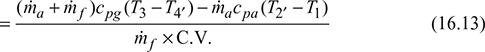
Network Wnet = Wt − Wc = (ṁa + ṁf) cpg (T3 − T4′) − ṁacpa (T2′ − T1)
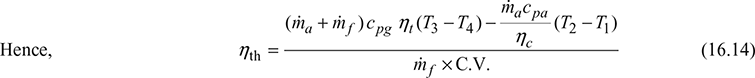
Heat supplied, Q = ṁf × C.V.
where CV = calorific value of fuel
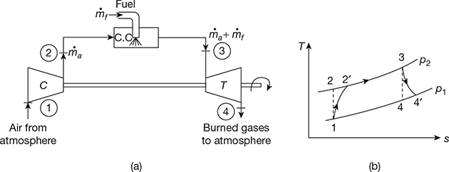
Figure 16.8 Open cycle constant pressure gas turbine: (a) Schematic diagram, (b) T-s diagrams
Leave a Reply