A gas turbine unit receives air at 100 kPa and 300 K and compresses it adiabatically to 620 kPa. The fuel has heating value of 44180 kJ/kg and fuel/air ratio is 0.017 kg fuel per kg air. The isentropic efficiencies of the compressor and the turbine are 88% and 90%, respectively. Calculate the compressor work, the turbine work, and the thermal efficiency.
Solution
The T-s diagram is shown in Fig. 16.40.
Given: p1 = 100 kPa, T1 = 300 K, p2 = 620 kPa, C.V. = 44180 kJ/kg,
F:A = 0.017 kg fuel/kg air, ηc = 0.88, ηt = 0.90
Refer to Fig. 16.40.
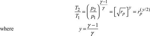
Isentropic process 1−2:
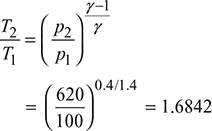
or T2 = 300 × 1.6842 = 505.3 K
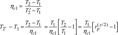
Compressor efficiency, ![]()
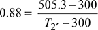
or T2′ = 533.3 K
Combustion process 2′−3:
ṁf × C.V. = ṁa × cpa (T3 − T2′) + ṁf × cpg (T3 − T2′)
Let cpa = 1.005 kJ/kgK and cpg = 1.15 kJ/kgK
0.017 × 44180 = (1 × 1.005 + 0.017 × 1.15) (T3 − 533.3)
= 1.0246 (T3 − 533.3)
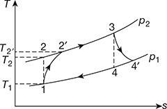
Figure 16.40 T-s diagram for gas turbine
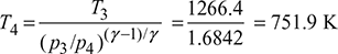
Isentropic process 3−4:
Turbine efficiency, ![]()
or ![]()
or T4′ = 803.3 K
Compressor work, wc = cpa (T2′− T1) = 1.005 (533.3 − 300) = 234.47 kJ/kg
Turbine work, 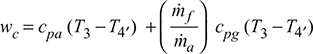
= (1.005 + 0.017 × 1.15) (1266.4 − 803.3) = 477.47 kJ/kg
Net work, wnet = wt − wc = 474.47 − 234.47 = 240 kJ/kg
Heat supplied, qs = ṁf × C.V. = 0.017 × 44180 = 751.06 kJ/kg
Thermal efficiency, ![]()
Example 16.19
The pressure ratio of an open cycle constant pressure gas turbine plant is 6. The temperature range of the plant is 20°C and 850°C. Using the following data; cpa = 1 kJ/kgK, cpg = 1.05 kJ/kgK, γa = γg = 1.4, C.V. of fuel = 44,000 kJ/kg, ηc = 0.85, ηt = 0.90, ηcomb = 0.95, find (a) the thermal efficiency of the plant, (b) the net power developed if circulation of air is 5 kg/s, (c) the air-fuel ratio, and (d) the specific fuel consumption.
Solution
Given: rp = 6, T1 = 273 + 20 = 293 K, T3 = 273 + 850 = 1223 K, cpa = 1 kJ/kgK
cpg = 1.05 kJ/kgK, γa = γg = 1.4, CV = 44,000 kJ/kg,
ηc = 0.85, ηt = 0.90, ηcomb = 0.95, ṁa= 5 kg/s
Refer to Fig. 16.40
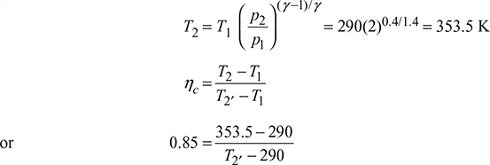
Isentropic process 1−2:
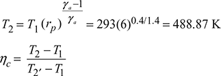
or T2′ = 523.43 K
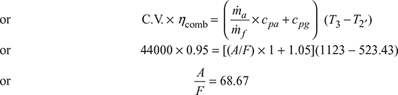
Combustion process 2′−3
ṁf × C.V. × ηcomb = (ṁa × cpa + ṁf × cpg) (T3 − T2′)
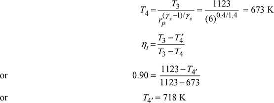
Isentropic process 3−4:
Compressor work, wc = cpa (T2′ − T1) = 1 × (523.43 − 293) = 230.43 kJ/kg
Turbine work, wt = ![]()
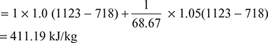
Net work per kg of air, wnet = wt − wc = 411.19 − 230.43 = 180.76 kJ/kg
Heat supplied, ![]()
- Thermal efficiency of plant,
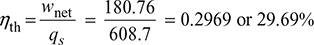
- Net power developed,P = ṁa × wnet = 5 × 180.76 = 903.8 kW
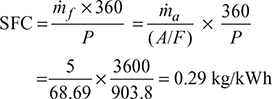
- Specific fuel consumption,
Example 16.20
Determine the efficiency of a gas turbine plant fitted with a heat exchanger of 75% effectiveness. The pressure ratio is 4:1 and the compression is carried out in two stages of equal pressure ratio with intercooling back to initial temperature of 290 K. The maximum temperature is 925 K. The isentropic efficiency of the turbine is 88% and the isentropic efficiency of each compressor is 85%. For air γ = 1.4, cp = 1.005 kJ/kgK.
Solution
The T-s diagram is shown in Fig. 16.41.
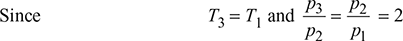
Given: ![]() T6 = 925 K, ηt = 0.88, ηc = 0.85, γ = 1.4, cp = 1.005 kJ/kgK.
T6 = 925 K, ηt = 0.88, ηc = 0.85, γ = 1.4, cp = 1.005 kJ/kgK.
Refer to Fig. 16.41.
L.P. compressor:
or T2′ = 364.7 K
∴ T4′ = 364.7 K for the H.P. compressor.
H.P. turbine:
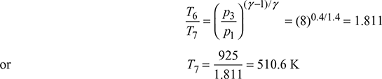
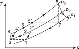
Figure 16.41 T-s diagram for gas turbine with intercooling
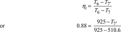
or T7′ = 560.3 K
Heat exchanger effectiveness, ![]()
or ![]()
or T5′ = 511.4 K
Heat supplied, qs = cp (T6 − T5′) = 1.005 (925 − 511.4) = 415.67 kJ/kg
Compressor work, wc = 2cp (T2′ − T1) = 2 × 1.005 (364.7 − 290) = 150.147 kJ/kg
Turbine work, wt = cp (T6 − T7′) = 1.005 (925 − 500.3) = 366.52 kJ/kg
Net work, wnet = wt − wc = 366.52 − 150.147 = 216.376 kJ/kg
Efficiency of the gas turbine, ![]()
Example 16.21
Air enters the compressor of a gas turbine plant operating on Brayton cycle at 1 bar and 27°C. The pressure ratio in the cycle is 6. Assuming the turbine work 2.5 times the compressor work, calculate the maximum temperature in the cycle and cycle efficiency. Take γ = 1.4
Solution
Given: p1 = 1 bar, T1 = 273 + 27 = 300 K, rp = 6, wt = 2.5 wc
Refer to Fig. 16.4 (b)
Process 1−2:
T2 = T1(rp)(γ − 1)/γ = 300(6)0.4/1.4 = 500.55 K
wc = cp (T2 − T1) = 1.005(500.55 − 300) = 201.55 kJ/kg
Process 3−4:
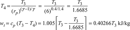
Now 0.40266 T3 = 2.5 × 201.55
or T3 = 1251.36 K
Maximum temperature is 1251.36 K.
Turbine work wt = 2.5 × 201.55 = 503.87 kJ/kg
Net work, wnet = wt − wc = 503.87 − 201.55 = 302.32 kJ/kg
Heat supplied, qs = cp (T3 − T2) = 1.005(1251.36 − 500.55)
= 754.564 kJ/kg
Cycle efficiency, ![]()
Example 16.22
A gas turbine cycle takes in air at 25°C and atmospheric pressure. The compression pressure ratio is 4. The isentropic efficiency of the compressor is 75%. The inlet temperature to turbine is limited to 750°C. What turbine efficiency would give overall cycle efficiency zero percent?
Solution
Given: T1 = 273 + 25 = 298 K, p1 = 1.013 bar,
rp = 4, ηc = 0.75, T3 = 273 + 750 = 1023 K
Refer to Fig. 16.40,
Process 1−2:
T2 = T1 (rp)(γ − 1)/γ = 298(4)0.4/1.4 = 442.8 K
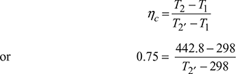
or T2′ = 491K
Process 3−4:
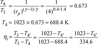
T4′ = 1023 − 334.6 ηt
Compressor work, wc = cp (T2′ − T1) = 1.005(491 − 298) = 193.96 kJ/kg
Turbine work, wt = cp (T3 − T4′) = 1.005(1023 − 1023 + 334.6 ηt)
= 336.27 ηt
Net work, wnet = wt − wc = 336.27 ηt − 193.96
Heat supplied, qs = cp (T3 − T2′) = 1.005(1023 − 491) = 534.66 kJ/kg
or 336.27 ηt − 193.96 = 0
or ηt = 0.5768 or 57.68%
Example 16.23
In a Brayton cycle gas turbine power plant, the minimum and maximum temperatures of the cycle are 300 K and 1200 K. The compression is carried out in two stages of equal pressure ratio with intercooling of the working fluid to the minimum temperature of the cycle after the first stage of compression. The entire expansion is carried out in one stage only. The isentropic efficiency of both compressors is 0.85 and that of the turbine is 0.9. Determine the overall pressure ratio that would give the maximum net work per kg working fluid. Derive the expression you use. γ = 1.4.
Solution
Given: T1 = T3 = 300 K, T5 = 1200 K, ![]() , ηc1 = ηc2 = 0.85, ηt = 0.90, γ = 1.4
, ηc1 = ηc2 = 0.85, ηt = 0.90, γ = 1.4
The T−s diagram is shown in Fig. 16.42.
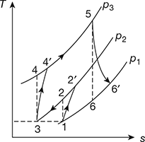
Figure 16.42 T-s diagram for gas turbine
Compressor 1:
Compressor 2:
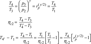
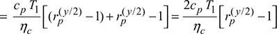
Compressor work, wc = wc1 + wc2 = cp [(T2 − T1) + (T4′ − T1)]
Turbine: 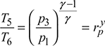
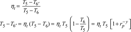
Turbine work, ![]()
Net work done, wnet = wt − wc
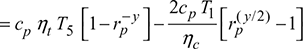
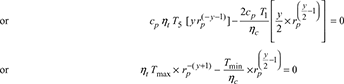
For maximum net work, ![]()

Example 16.24
In an open-cycle gas turbine plant, air enters at 15°C and 1 bar, and is compressed in a compressor to a pressure ratio of 15. The air from the exit of compressor is first heated in a heat exchanger which is 75% efficient by turbine exhaust gas and then in a combustor to a temperature of 1600 K. The same gas expands in a two-stage turbine such that the expansion work is maximum. The exhaust gas from HP turbine is reheated to 1500 K and then expands to LP turbine. The isentropic efficiencies of compressor and turbine may be taken as 86% and 88%, respectively. The mechanical efficiencies of compressor and turbine are 97% each. The alternator efficiency is 98%. The output of turbo-alternator is 250 MW. Sketch the system and show the process on T-s diagram, Determine (a) the cycle thermal efficiency, (b) the work ratio, (c) the specific power output, and (d) the mass flow rate of air.
Solution
The schematic is shown in Fig. 16.43(a) and T-s diagram in Fig. 16.43(b).
- ηc = 0.86, ηt = 0.88, ηalt = 0.98, (ηmech)c = (ηmech)t = 0.97
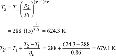
 Figure 16.43 Open cycle gas turbine: (a) Schematic, T-s diagramCompressor work,
 For maximum expansion work,
 p5 = pi = 3.873 barT5 =
  = 1600
  = 1086.7 Kηt1 =
  or T5′ = T4 − ηt1 (T4 − T5)= 1600 − 0.88 (1600 − 1086.7) = 1158.5 KT7 = T6
  p7 = p1 = 1 bar, p6 = pi = 2.873 barT7 = 1500
  = 1018.8 Kηt2 =
  or T7′ = 1500 − 0.88 (1500 − 1018.8) = 1076.5 KTurbine work,wt = wt1 + wt2= 1.005 [(1600 − 1158.5) + (1500 − 1076.5)] × 0.97= 843.245 kgNet work, wnet = wt − wc= 843.245 − 405.2 = 438.045 kJ/kgHeat exchanger effectiveness =
  or 0.75 =
  or T3′ = 977.15 KHeat supplied = 1.005 [(1600 − 977.15) + (1500 − 1158.5)] = 969.17 kJ/kgThermal efficiency,ηth =
  = 0.452 or 45.2%
 - Work ratio =
 = 0.5195.
 - Specific power output1 × wnet = 1 × 438.045 = 438.045 kW
- Mass flow rate of air =
 =
=  = 559.3 kg/s
Example 16.25
A gas turbine utilises a two-stage centrifugal compressor. The pressure ratios for the first and second stages are 2.5 and 2.1, respectively. The flow of air is 10 kg/s, this air being drawn at 1.013 bar and 20°C. If the temperature drop in the intercooler is 60°C and the isentropic efficiency is 90% for each stage, calculate:(a) the actual temperature at the end of each stage and (b) the total compressor power. Assume γ = 1.4 and cp= 1.005 kJ/kgK for air.
Solution
Given: rp1 = 2.5, rp2 = 2.1, ṁa = 10 kg/s, p1 = 1.013 bar, T1 = 20 + 273 = 293 K, ∆T2 = 60°C, ηi1 = ηi2 = 0.9, γ = 1.4, cp = 1.005 kJ/kgK.
The T–s diagram is shown in Fig. 16.44.
 = 1.299or T2 = 380.68 Kηi1 =
  or 0.9 =
  or T2′ = 390.42 K or 117.42°CTemperature at the end of first stage is 117.42°C.Temperature at the inlet of second stage= 117.42 – 60 = 57.42°CT3 = 57.42 + 273 = 330.42 K
 Figure 16.44 T-s diagramor T4 = 408.44 Kηi2 =
  0.9 =
0.9 =  Temperature at the end of second stage,T4′ = 417.11 K or 144.1°C
- Pc1 = ṁacp (T2′ – T1) = 10 × 1.005 (390.42 – 293) = 979.07 kJ/sPc2 = ṁacp (T4′ – T3) = 10 × 1.005 (417.11 – 330.42) = 877.23 kJ/sTotal compressor power,Pc = Pc1 + Pc2 = 979.07 + 871.23 = 1850.3 kW
Example 16.26
An open cycle gas turbine takes in air at 300 K and 1 bar and develops a pressure ratio of 20. The turbine inlet temperature is 1650 K. The polytropic efficiency of the compressor and the turbine each is 90%. The pressure loss in the combustor is 3% and the alternator efficiency is 97%. Take cpa= 1.005 kJ/kgK and cpg = 1.128 kJ/kgK for air and gas, respectively. The calorific value of fuel is 42 MJ/kg. Determine the overall efficiency, the specific power output, the fuel to air ratio and the specific fuel consumption.
Solution
Given: T1 = 300 K, p1 = 1 bar, rp = 20, T3 = 1650 K, hc = ht = 0.90, ∆p2 = 3%, halt = 0.97, cpa = 1.005 kJ/kgK, cpg = 1.128 kJ/kgK, C.V. = 42 MJ/kg
The T–s diagram is shown in Fig. 16.45.
Compressor process 1–2′:

or T2 = 300 × 2.3535 = 706 K
ηc = ![]()
or 0.9 = ![]()
or T2′ = 747.8 K
p2 = 20 × 1 = 20 bar
p3 = 0.97 × 20 = 19.4 bar
Combustion process 2′–3:
ṁf × CV = ṁf × cpa (T3 – T2′) + ṁf × cpg (T3 – T2′)
= (ṁa × cpa + ṁf × cpg) (T3 – T2′)

or ṁf × 42 × 103 = (ṁa × 1.005 + ṁf × 1.128) (1650 – 747.8)
= 906.7 ṁa + 1017.7 ṁf
or 40982.3 ṁf = 906.7 ṁa

Turbine process 3–4′:

γg = ![]() , R = cpg – cvg, cvg = cpg – R = 1.128 – 0.287 = 0.841 kJ/kgK
, R = cpg – cvg, cvg = cpg – R = 1.128 – 0.287 = 0.841 kJ/kgK
γg = ![]() = 1.34
= 1.34
T4 =  = 777.5 K
ηt = ![]()
or 0.9 = ![]()
or T4′ = 864.75 K
Specific power output:
wnet = wt – wc = cpg (T3 – T4′) – cpa (T4′ – T1)
= 1.128 (1650 – 864.75) – 1.005 (747.8 – 300)
= 435.72 kJ/kg of air
Overall efficiency, ηoverall = ![]() =0.4281 or 42.81%
=0.4281 or 42.81%
Specific fuel consumption = 
=  = 0.1828 kg/kWh
Leave a Reply