The basic cycle of a turbo-jet engine in T-s diagram is shown in Fig. 17.7. The various processes are as follows:
Process 1−2: Isentropic diffusion of atmospheric air from velocity c1 to c2 = 0 with diffuser efficiency of 100%. 1−2′ is the actual diffusion with diffuser efficiency ηd from p1 to p2.
Process 2′−3: Isentropic compression of air in the compressor from p2 to p4. Process 2′–3′ is the actual compression with compressor efficiency ηc.
Process 3−4: Ideal heat addition at pressure p4. Process 3′-4 is the actual heat addition at pressure p4.
Process 4−5: Isentropic expansion of gas in the turbine from p4 to p3. Process 4−5′ is the actual expansion in the turbine with turbine efficiency ηt.
Process 5′−6: Isentropic expansion of gas in the nozzle from p3 to p1. Process 5′−6′ is the actual expansion of gas in the nozzle with nozzle efficiency ηn.
Consider 1kg of working fluid flowing through the system.
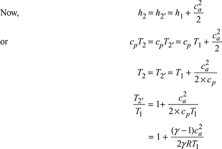
Diffuser:
The energy equation between states 1 and 2 is as follows:
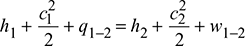
In an ideal diffuser, c2 = 0, q1–2 = 0 and w1–2 = 0


where cpa = specific heat of air at constant pressure

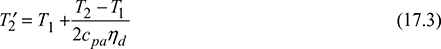
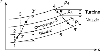
Figure 17.7 T-s diagram for turbo-jet
Compressor:
Energy equation between state 2′ and 3:
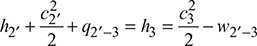
Compressed work, ![]()
Assuming c3 ≃ c2′, and q2′–3 = 0, we have
wc = h3 − h2′ = cpa (T3 − T2′)
Actual compressor work, wca = h3′ − h2′

Combustion chamber:
Ideal heat supplied, q = q3′ − 4 = h4 − h3′


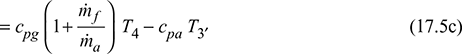
where cpg = specific heat of gas at constant pressure
Turbine:
Energy equation between states 4 and 5:
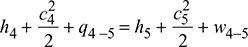
If q4-5 = 0, then
Turbine work, ![]()
If c4 ≃ c5, then


now wta = wca
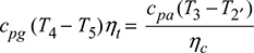
If cpa = cpg = cp, then
T5′ = T4 − (T4 − T5)ηt

Jet nozzle:
Energy equation between states 5′ and 6:
Ideal case: ![]()
Actual case: ![]()
If c5′ ≃ 0 as compared to c6′, then
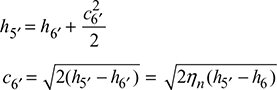

Thermal efficiency, ![]()
1 Thrust
Let ca = forward velocity of aircraft through air, m/s
= velocity of approach, assuming surrounding air velocity to be zero.
cj = velocity of jet of gases relative to the aircraft, m/s
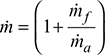 , mass rate of flow of products leaving the nozzle per 1kg of air.
Absolute velocity of gases leaving the aircraft = cj − ca
Absolute velocity of air entering the aircraft = 0
∴ Change of momentum = ṁ (cj − ca)


2 Thrust Power
It is defined as the rate at which work must be developed by the engine if the aircraft is to be kept moving at a constant velocity ca against friction force or drag.
Thrust power, T.P. = forward thrust × speed of aircraft

3 Propulsive Power
The energy required to change the momentum of the mass flow of gases represents the propulsive power. It is expressed as the difference between the rate of kinetic energies of the entering air and exit gases.


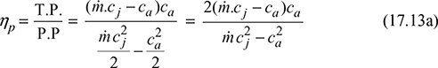
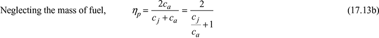
4 Propulsive Efficiency
It is defined as the ratio of thrust power to propulsive power.
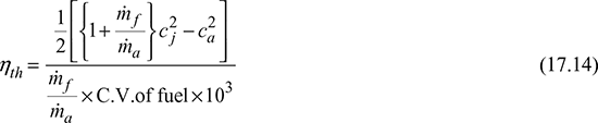
5 Thermal Efficiency
It is defined as the ratio of propulsive work to the energy released by the combustion of fuel.
6 Overall Efficiency
Overall efficiency, 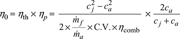
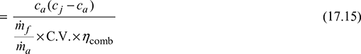
for η0 to be maximum, ![]()
cj − 2ca = 0

Therefore, for maximum overall efficiency, the aircraft velocity is one-half of the jet velocity.
7 Jet Efficiency
Jet efficiency is defined as follows:

8 Ram Air Efficiency
In Fig. 17.2(b), process 1-2′ is the ramming process during which the total energy or stagnation enthalpy remains unchanged, if the process is assumed adiabatic, while pressure of air increases. Process 1-2 is the ideal ramming action.


Leave a Reply