This cycle is composed of four internally reversible processes, two adiabatic and two constant volume processes. The p-v and T-s diagrams are shown in Fig. 9.6. The various processes are:
Process 1−2: Isentropic compression.
Process 2−3: Constant volume heat addition.
Process 3−4: Isentropic expansion.
Process 4−1: Constant volume heat rejection.
This cycle is used for spark ignition (petrol) engines.
Consider 1 kg of air flowing through the cycle. Since the air in the cylinder acts as a closed system, from first law of thermodynamics for isentropic compression and expansion, we have
q − w = Δu
For constant volume heat supplied and rejection processes, since w = 0,
q = Δu = cv ΔT

Figure 9.6 Otto cycle: (a) p-v diagram, (b) T-s diagram
Heat supplied qs = q2−3 = cv(T3 – T2)
Heat rejected qr = q4−1 = cv (T4 – T1)
Work done per cycle, wnet = qs – qr = cv(T3 – T2) – cv(T4 – T1)
Air standard (or thermal) efficiency = ![]()
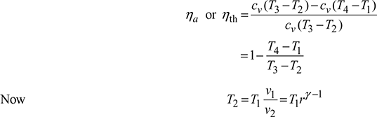
where ![]()

where ![]() pressure ratio
pressure ratio


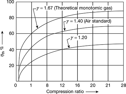
Figure 9.7 Otto cycle thermal efficiency v’s compression ratio
The air standard efficiency of Otto cycle depends on compression ratio only and increases as compression ratio increases (Fig. 9.7). In actual engine working on Otto cycle, the compression ratio varies from 5 to 8. This engine is used for spark ignition engines working on petrol.
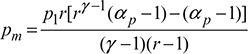
Mean Effective Pressure (m.e.p.). It may be defined as the ratio of work done to the displacement volume of piston.
Work done, w = cv[(T3 – T2) – (T4 – T1)]
Displacement volume, vs = v1 – v2
M.E.P., 


Leave a Reply