The schematic diagram of vapour absorption system is shown in Fig. 19.23. It consists of
- an absorber,
- a pump,
- a generator and
- a pressure reducing valveThe function of the pressure reducing valve is to replace the compressor of vapour compression system. The other components of the system are
- condenser,
- receiver,
- expansion valve and
- evaporator as in the vapour compression system.
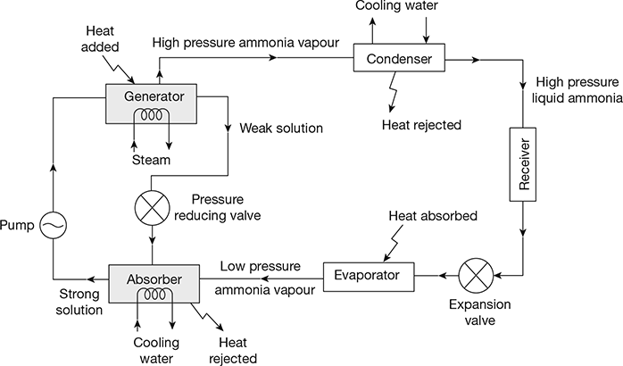
Figure 19.23 Schematic diagram for vapour absorption system
1 Working
In the vapour absorption system, the low pressure ammonia vapour leaving the evaporator, enters the absorber where it is absorbed by the cold water in the absorber. The solution of ammonia vapour in water is called aqua-ammonia. The absorption of ammonia vapour in water lowers the pressure in the absorber which in turn draws more ammonia vapour from the evaporator. As a result of this, the temperature of solution rises. Some cooling arrangement (usually water cooling) is employed in the absorber to remove the heat of solution evolved there. This increases the absorption capacity of water. The strong solution thus formed in the absorber is pumped to the generator by the liquid pump.
The strong ammonia solution in the generator is heated by some external source such as hot gas, steam or heating oil. During the heating process, the ammonia vapour is driven off the solution at high pressure leaving behind the hot weak solution of ammonia in the generator. This weak ammonia solution flows back to the absorber at low pressure after passing through the pressure reducing valve. The high pressure ammonia vapour from the generator is condensed in the condenser to a high pressure liquid ammonia. This liquid ammonia is passed to the expansion valve through the receiver and then to the evaporator. This completes the vapour absorption cycle.
Leave a Reply