The schematic arrangement of a single-stage reciprocating compressor is shown in Fig. 12.3. It consists of a cylinder with cooling jacket, piston, connecting rod, crank, suction valve, and delivery valve. The piston will be making to-and-fro motions through the crankshaft arrangement and generally run by an electric motor, diesel engine, petrol engine, or steam engine. During the outward motion of the piston, the pressure inside the cylinder falls below the atmospheric pressure and the suction valve is opened due to the pressure difference. The atmospheric air is then drawn into the cylinder until the piston reaches the bottom dead centre position.
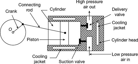
Figure 12.3 Single-stage reciprocating air-compressor
As the piston starts move inwards, the suction valve gets closed and the pressure starts increasing until the pressure inside the cylinder is more than the pressure of the delivery side. Then the delivery valve opens and high pressure air is delivered to the receiver till the piston reaches the top dead centre. At the end of the delivery stroke, the small volume of high pressure air left in the clearance volume expands as the piston starts moving outwards. Hence, the cycle is repeated.
Leave a Reply