1 Four-stroke Spark-ignition Engine
The details of various processes of a four-stroke spark-ignition engine with overhead valves are shown in Fig. 10.5. Within the four strokes, there are five events to be completed namely, suction, compression, combustion, expansion, and exhaust.
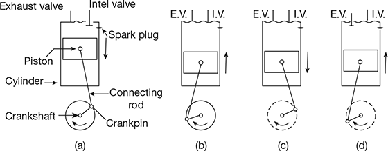
Figure 10.5 Working principle of a four-stroke SI engine: (a) Suction stroke, (b) Compression stroke, (c) Expansion or power stroke, (d) Exhaust stroke
- Suction stroke: It starts when the piston is at the top dead centre (TDC) and is about to move downwards. The inlet valve is open and the exhaust valve is closed at this time. The charge consisting of the fuel-air-mixture is drawn into the cylinder. When the piston reaches the bottom dead centre (BDC), the suction stroke ends and the inlet valve closes.
- Compression stroke: The charge is compressed to the clearance volume by the return stroke of the piston with both inlet and exhaust valves are closed. At the end of the compression stroke, the mixture is ignited with the help of spark plug to convert chemical energy of fuel to heat energy.
- Expansion stroke: The high pressure of burnt gases forces the piston towards BDC with both the valves in closed position to produce power.
- Exhaust stroke: At the end of the expansion stroke, the exhaust valve opens with the inlet valve closed. The piston starts moving towards the TDC and sweeps the burnt gases out from the cylinder. The exhaust valve closes when piston has reached TDC.
2 Four-stroke Compression-ignition Engine
The four cycles of operation of a CI engine are shown in Fig. 10.6.
- Suction stroke: Only air is induced during the suction stroke with the inlet valve open and the exhaust valve closed.
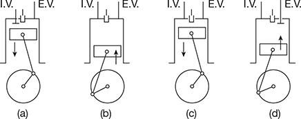 Figure 10.6 Cycle of operation of a four-stroke CI engine: (a) Suction, (b) Compression, (c) Expansion, (d) Exhaust
 - Compression stroke: The sucked air is compressed into the clearance volume with both valves closed.
- Expansion stroke: Fuel injection starts nearly at the end of the compression stroke, resulting in combustion. The products of combustion expand and both the valves remain closed.
- Exhaust stroke: The piston moves from BDC to TDC and pushes out the products of combustion with the exhaust valve open and intake valve closed.
3 Two-stroke Spark-ignition Engine
In a two-stroke engine, the cycle is completed in one revolution of the crankshaft. The filling process is accomplished by the charge compressed in the crankcase or by a blower. The induction of the compressed charge moves out the products of combustion through the exhaust ports. Therefore, two piston strokes are required for these two operations. Two strokes—one for compressing the fresh charge and the other for expansion or power stroke—are sufficient to complete the cycle. Figure 10.7 shows the crankcase scavenged two-stroke engine.
4 Two-stroke Compression-ignition Engine
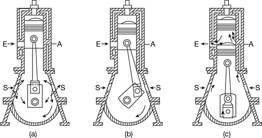
Figure 10.8 shows a two-stroke compression-ignition engine. It is a crankcase scavenged type engine. S is the plate valve for admission of air in the crank case, E is the exhaust port, and A is the port in the cylinder communicating to the crankcase through the cylinder block casting; cams and valves are not required. The four operations—air induction, air compression and fuel injection, expansion, and exhaust are completed in two strokes, that is, in one revolution of crankshaft.
In the upward motion of the piston, suction is created in the crankcase and air enters through the plate valves for full 180° of crank rotation as shown in Fig. 10.8(a). Above the piston, the compression starts after both the points have been covered by the piston. At the end of compression, fuel is injected and ignites at TDC giving products of combustion at high pressure.
On downward stroke, the high pressure products of combustion expand and the air below the piston compresses, closing the plate valves, as shown in Fig. 10.8(b). As soon as the piston uncovers the exhaust port, the products of combustion are released into the atmosphere. A little later, on the downward stroke, the other port communicating with the crankcase gets uncovered and the air compressed in the crankcase gets transferred to the space above the piston as shown in Fig. 10.8(c).
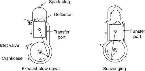
Figure 10.7 Crankcase scavenged two-stroke SI engine
Leave a Reply