The steam passes to the fixed blades with velocity va1. Fixed blades also act as nozzles with pressure drop occurring, while steam passes through them so that there is gain in kinetic energy and steam leaves the fixed blades with velocity va2. The expansion of steam and the enthalpy drop occur in fixed and moving blades. The velocity diagrams for an impulse-reaction turbine are shown in Fig. 7.11.
- Degree of Reaction: The degree of reaction Rd of a reaction turbine is defined as the ratio of enthalpy drop over moving blades to the total enthalpy drop in the stage. Thus
 Enthalpy drop through fixed blades,
  Enthalpy drop along the moving blades, ∆hm =
  Kinetic energy supplied to moving blades, K.E.
 Neglecting friction of blade surface,
 Axial thrust on rotor = (vf 1 − vf 2) + (∆p)m × area of blade discNow total enthalpy drop in the stage = Work done by steam in the stage Δhf + Δhm = u (vw1 + vw2)
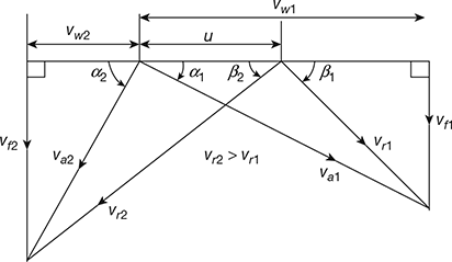 Figure 7.11 Velocity diagrams for impulse-reaction turbine
  From Fig. 7.11, we havevr2 = vf2 cosec β2 and vr1 = vf1 cosec β1and vw1 + vw2 = vf 1 cot β1 + vf 2 cot β2The velocity of flow generally remains constant through the blades.∴ vf 1 = vf 2 = vf
 If Rd = 0.5, then
 From Fig. 7.11, we have u = vf (cot β2 − cot α2) = vf (cot α1 − cot β1)
 This means that the moving and fixed blades must have the same shape if the degree of reaction is 50%. This condition gives symmetrical velocity diagrams. This type of turbine is known as Parson’s Reaction Turbine.
 - Efficiency: We assume that the degree of reaction is 50%, that is, ∆hf = ∆hm, the moving and fixed blades are of the same shape, and the velocity of steam at exit from the preceding stage is the same as the velocity of steam at the entrance to the succeeding stage.The work done per kg of steam, w = u(vw1 + vw2) = u [va1 cos α1 + (vr2 cos β2 − u)]Now, β2 = α1 and vr2 = va1

 where
where  is the speed ratio.K.E. supplied to fixed blade =
  K.E. supplied to moving blade
  Total energy supplied to stage,
 For symmetrical blades, vr2 = va1
 From Fig. 7.11, we have


 For ηb to be maximum,
  (1 + 2ρ cos α1 − ρ2) (4 cos α1 − 4ρ) − 2ρ (2 cos α1 − ρ) (2 cos α1 − ρ) = 04 (cos α1 − ρ) (1 + 2ρ cos α1 − ρ2) − 4ρ (cos α1 − ρ) (2 cos α1 − ρ) = 0(cos α1 − ρ) [(1 + 2ρ cos α1 − ρ2) − ρ (2 cos α1 − ρ)] = 0∴ cos α1 − ρ2 = 0

- Height of Turbine Blading:The height and thickness of blading are shown in Fig. 7.12.Volume flow = Area × flow velocity
 where d = mean diameter of turbine wheel h1, h2 = blade heights at inlet and outlet respectively t1, t2 = thickness of blades at inlet and outlet respectively. n = number of blades
 Figure 7.12 Height of turbine bladingFor most of the turbines, vf1 = vf2 = vf, h1 = h2 = h and t1 = t2 = t
 Equation (7.31) gives height of blades.The pitch of blades, p is given by: ṁvs = [n (p – t)h] vfGenerally t << p, ∴ ṁvs = n ph vf = π dhvf
Leave a Reply