The velocity diagrams at inlet and outlet of the impeller for the centrifugal compressor are shown in Fig. 14.6(a).

Figure 14.6 (a) Actual velocity diagrams
u1 = mean blade velocity at entrance
u2 = mean blade velocity at exit
va1 = absolute velocity at inlet to rotor
va2 = absolute velocity at outlet to rotor
vr1 = relative velocity at inlet to rotor
vr2 = relative velocity at outlet to rotor
vw1 = velocity of whirl at inlet
vw2 = velocity of whirl at outlet
vf1 = velocity of flow at inlet
vf 2 = velocity of flow at inlet
D1, D2 = mean diameter of rotor at inlet and outlet, respectively
α1 = exit angle from stator or guide vanes at entrance
β1 = inlet angle to rotor in impeller blade angle at inlet
α2 = inlet angle to the diffuser or the stator
β2 = outlet angle from rotor or impeller blade angle at outlet.
If it is assumed that the entry of the air to the rotor is axial, then whirl component vw1 = 0 and va1 = vf1.
1 Theory of Operation
- Ideal Velocity DiagramsBy Newton’s second law of motion, the rate of change of angular momentum of air is equal to the torque applied to the body causing that change. Considering 1 kg/s of mass flow rate of air,
 where
where 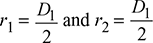 For ideal case, let us assume that the impeller is radial vaned, and there is no frictional loss, no heat transfer and the air leaves the impeller with a tangential velocity vw2 = u2. Also for axial entry, vw1 = 0
 Work done by impeller for 1 kg/s air flow rate,
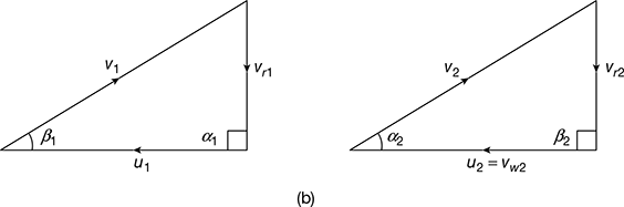 Figure 14.6(b) Ideal velocity diagramswhere ω = angular speed of rotor, rad/sNow, r2ω = u2
 Since air cannot leave the impeller at a velocity greater than the impeller tip velocity, Eq. (14.11) gives the maximum work capacity of the impeller.Also, by steady flow energy equation, we have
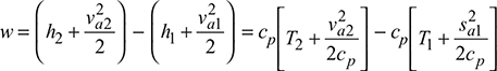

 In most practical problems,va1 = va2
 = h2 − h1
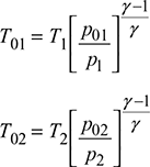
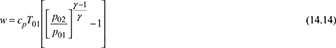
 where
where  = stagnation pressure ratio
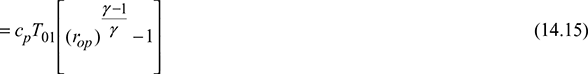
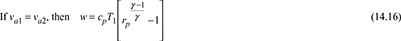 where,
  = static pressure ratioComparing Eq. (14.11) and (14.14), we have
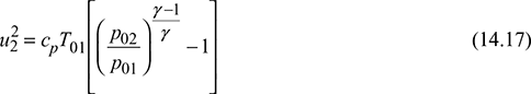
 If va1 = va2, then
 Total temperature increase across an impeller,
 where ṁ = mass flow rate of air, kg/s, and u2 is in m/s.Therefore, for a centrifugal compressor working under ideal condition, the power input depends on the following:
- The mass flow rate of airThe total pressure ratio of the compressor which, in turn, depends on the square of the impeller velocityThe total inlet temperatureThe total inlet temperature rise between the inlet and outletThere is a maximum work capacity of an impeller depending on the tip velocity
- Inlet temperature
- Square of the impeller velocity
- It is independent of the impeller diameter
- Actual Velocity DiagramsThe actual velocity diagrams are shown in Fig. 14.7.Theoretical torque, T = vw2r2 – vw1r1Work done on 1 kg/s of air.w = (vw2r2 – vw1r1)wwhere, ω = angular speed of rotor, rad/s

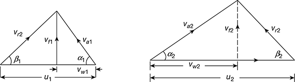 Figure 14.7 Actual velocity diagrams for centrifugal compressor
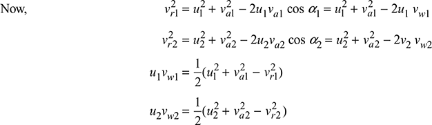
 = ΔKE + Δp due to diffusion action + Δp due to centrifugal actionTherefore, the fraction of kinetic energy imparted to air and converted into pressure energy in impeller is given by,
 where ρ = density of air.If va1 = diffuser outlet velocity, then
2 Width of Blades of Impeller and Diffuser
Air mass flow rate per second,
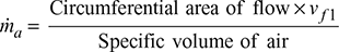
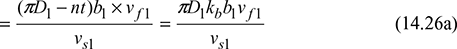
where, vs = specific volume of air
b1, b2 = width or height of impeller blades at inlet and outlet, respectively
kb = blade factor
n = number of blades
t = thickness of blades
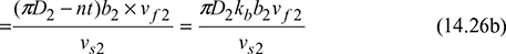
The width or height of the diffuser blades at the outlet is given by,
where suffix ‘d’ represents the quantities at the diffuser outlet. The width or height of the diffuser blades at the inlet is the same as that of the impeller blades at outlet.
Leave a Reply