An obstacle placed between a noise source and a receiver is termed a barrier or screen. When a sound wave approaches the barrier, some of the sound wave is reflected and some is transmitted past (see Figure 9.38). At high frequency, barriers are quite effective, and a strong acoustic “shadow” is cast. At low frequency (when the wavelength can equal or exceed the barrier height), the barrier is less effective, and some sound is diffracted into the shadow zone. Indoors, barriers are usually partial walls. Outdoors, the use of walls, earth berms, and even buildings can protect residential areas from traffic and industrial noise sources [116, 117].
The use of barriers to control noise problems is an example of a practical application of a complicated physical theory: the theory of diffraction, a physical phenomenon that corresponds to the nonspecular reflection or scattering of sound waves by an object or boundary. Most of the theories of diffraction were originally formulated for optics, but they find many applications in acoustics. As in the diffraction of light waves, when the sound reaches a listener by an indirect path over a barrier, there is a shadow zone and a bright zone, as shown in Figure 9.38. However, the diffracted wave coming from the top edge of the barrier affects a small transition region close to the shadow zone by interfering with the direct wave [118].
Certainly, from a practical point of view, most of the applications of the physical and geometrical theory have been difficult to use due to the complexity of the analysis, which does not permit fast calculation for design purposes. Because of this, several algorithms, charts, and plots have been developed from time to time to determine the insertion loss or reduction in sound pressure level expected after installation of a barrier both indoors and outdoors.
Figure 9.39 shows the insertion loss or reduction in sound pressure level expected after installation of a semi‐infinite barrier in free space between a source and receiver. In Figure 9.39, N is the dimensionless Fresnel number related to the shortest distance over the barrier rs + rr and the straight line distance r0 between the source S and receiver R:
(9.49)![]()
where λ is the wavelength and rs and rr are shown in Figure 9.39. Usually δ = rs + rr − r0 is called the path length difference. It can be observed in Figure 9.39 that when a noise source approximates to an incoherent line source (e.g. stream of traffic), then the attenuation is lower than the one calculated for a point source.
9.7.1 Transmission Loss of Barriers
Barriers are a form of partial enclosure (they do not completely enclose the source or receiver) to reduce the direct sound field radiated in one direction only. The barrier edges diffract the sound waves, but some waves can pass through the barrier according to the sound transmission laws. All the theories of diffraction have been developed assuming that the transmission loss of the barrier material is sufficiently large that transmission through the barrier can be ignored. Obviously, the heavier the barrier material, or the higher the frequency, the greater is the transmission loss for sound traveling through the barrier. A generally applicable acoustical requirement for a barrier material is to limit the component of sound passing through it to 10 dB less than the predicted noise level due to sound diffracted over the barrier.
Evidently, this is not a governing criterion for concrete or masonry, but can be important for light aluminum, timber, and for glazing panels. In addition, this may be an important consideration when designing “windows” in very tall barriers.
In a study on barriers used indoors, Warnock compared the transmitted sound through a barrier with the diffracted sound over the barrier [119]. He found that the transmitted sound is negligible if the surface density of a single screen satisfies the criterion ρs = 3 ![]() kg/m2. The minimum acceptable value of ρs corresponds to the transmission loss at 1000 Hz being 6 dB greater than the theoretical diffraction loss. A formula for calculating the minimum required surface density for a barrier is [120]
kg/m2. The minimum acceptable value of ρs corresponds to the transmission loss at 1000 Hz being 6 dB greater than the theoretical diffraction loss. A formula for calculating the minimum required surface density for a barrier is [120]
(9.50)![]()
where A is the A‐weighted potential attenuation of the barrier in decibels when it is located outdoors.
As a general rule, when the barrier surface density ρs exceeds 20 kg/m2, the transmitted sound through the barrier can be ignored, and then the diffraction sets the limit on the noise reduction that may be achieved.
According to the discussion above, when butting or overlapping components are used to assemble a noise barrier, it is important that the joints be well sealed to prevent leakage. As an indication, it is common for timber barriers to be manufactured from 19‐mm‐thick material. As indicated by the mass law, this provides a sound reduction index of 20 dB if joints are tight, which is quite sufficient for barriers designed to provide an attenuation of 10 dB. In some countries, the legislation requires a sample of barrier to be tested in accordance with the local standard for sound insulation of partitions in buildings.
9.7.2 Use of Barriers Indoors
Single‐screen barriers are widely used in open‐plan offices (or landscaped offices) to separate individual workplaces to improve acoustical and visual privacy. The basic elements of these barriers are freestanding screens (partial‐height partitions or panels). However, when a barrier is placed in a room, the reverberant sound field and reflections from other surfaces cannot be ignored.
The diffraction of the sound waves around the barrier boundaries alters the effective directivity of the source. For a barrier placed in a rectangular room, if the receiver is in the shadow zone of the barrier and the sound power radiated by the source is not affected by insertion of the barrier, the approximate insertion loss (the reduction of the sound pressure level before and after the erection of the barrier) can be calculated by [121]
(9.51)
where Qθ is the source directivity factor, r is the distance between the source and receiver without the barrier, S0 α0 is the room absorption for the original room before placement of the barrier, S0 is the total room surface area, α0 is the mean room Sabine absorption coefficient, S is the open area between the barrier perimeter and the room walls and ceiling,
(9.52)
is the effective directivity, n is the number of edges of the barrier (e.g. n = 3 for a freestanding barrier, see Figure 9.40). The parameters Γ1 and Γ2 are dimensionless numbers related to the room absorption on the source side (S1 α1) and the receiver side (S2 α2) of the barrier, respectively, as well as the open area, and are given by
(9.53)![]()
Note that S1 + S2 = S + (area of two sides of the barrier) and α1 and α2 are the mean Sabine absorption coefficients associated with areas S1 and S2, respectively.
It is seen that when the barrier is located in a highly reverberant field the IL tends to zero. This means that the barriers are ineffective in highly reverberant environments. Consequently, in this case the barrier should be treated with sound‐absorbing material, increasing the overall sound absorption of the room.
The approximation for the effective directivity given in Eq. (9.52) is based on Tatge’s result [122]. In deriving Eq. (9.51) the interference between the sound waves has been neglected, so Eq. (9.51) predicts the insertion loss accurately when octave‐band analysis is used. However, the effects of the reflections by the floor and the ceiling are not taken into account. This effect will be discussed later. In general, the ceiling in an open‐plan office must be highly sound absorptive to ensure maximum performance of a barrier. This is particularly important at those frequencies significant for determining speech intelligibility (500–4000 Hz).
A more general model for calculating the insertion loss of a single‐screen barrier in the presence of a floor and a ceiling has been presented by Wang and Bradley [123]. Their model was developed using the image source technique. More recently, Lau and Tang [124] have presented a study on the insertion loss provided by rigid noise barriers in an enclosed space using different approaches.
EXAMPLE 9.13
A machine source operates on the floor of a building of dimensions 30 m × 30 m with a height of 10 m. Suppose the average absorption coefficient is ![]() = 0.02 at 500 Hz. A receiver is located 15 m away from the machine. A wall‐to‐wall 5‐m high barrier is built right in the middle between the source and the receiver. The barrier is made of metal plates with an absorption coefficient of α = 0.02 at 500 Hz. Consider the case that the receiver and the acoustical center of the machine are 1 m above the floor. Estimate the insertion loss of the barrier for the 500‐Hz one-octave band.
= 0.02 at 500 Hz. A receiver is located 15 m away from the machine. A wall‐to‐wall 5‐m high barrier is built right in the middle between the source and the receiver. The barrier is made of metal plates with an absorption coefficient of α = 0.02 at 500 Hz. Consider the case that the receiver and the acoustical center of the machine are 1 m above the floor. Estimate the insertion loss of the barrier for the 500‐Hz one-octave band.
SOLUTION
The room surface area S0 = 2(900) + 4(300) = 3000 m2. The surface of the barrier is 150 m2 and the open area between the barrier perimeter and the room walls and ceiling is also 150 m2. Due to the symmetry of the problem, the surfaces forming the room on the source and receiving side of the barrier are S1 = S2 = 150 + S0/2 = 1650 m2. In addition, α1 = α2 = 0.02 and S1 α1 = S2 α2 = 33 m2. We assume that the machine is an omnidirectional source situated on a hard floor, i.e. Qθ ≈ 2. Now we determine the geometrical distances:

The wavelength λ = 344/500 = 0.688 m, and the Fresnel number N = 2δ/λ = 5.81. Now, as the barrier extends all the way across the room, the sound is diffracted over the top of the barrier only, so

Therefore, inserting these values in Eq. (9.51), we obtain
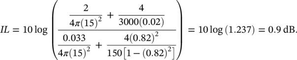
We observe that, although the receiver is deep in the shadow zone of the barrier (N = 5.81), the IL is insignificant as compared to the open space situation. If barriers are used inside buildings, their performance is often disappointing because sound can propagate into the shadow zone by multiple reflections. To produce acceptable attenuation, it is important to suppress these reflections by the use of sound‐absorbing material, particularly on ceilings just above the barriers.
An ISO standard has been published with guidelines for noise control in offices and workrooms by use of acoustical screens [125]. The standard specifies the acoustical and operational requirements to be agreed upon between the supplier or manufacturer and the user of acoustical screens. In addition, the standard is applicable to (i) freestanding acoustical screens for offices, service areas, exhibition areas, and similar rooms, (ii) acoustical screens integrated in the furniture of such rooms, (iii) portable and removable acoustical screens for workshops, and (iv) fixed room partitions with more than 10% of the connecting area open and acoustically untreated.
9.7.3 Reflections from the Ground
When considering the reflections of sound from the ground, extra propagation paths are created that can result in increased sound pressure at the receiver. The geometry showing reflections from acoustically hard ground with an infinite barrier is shown in Figure 9.41. Application of the image source method indicates that a total of four diffraction paths must be considered: SOR, SAOBR, SAOR, and SOBR. Therefore, the attenuation and expected sound pressure level at the receiver has to be calculated for each of the four paths. Then, the four expected sound pressure levels are combined logarithmically to obtain the sound pressure level at the receiver. The process is repeated for the case without the barrier (which has just two paths) to calculate the combined level at the receiver before placement of the barrier. Then, the insertion loss is determined as usual. If the barrier is finite, eight separate paths should be considered since the diffraction around the ends involves only one ground reflection.
Usually, the ground is somewhat absorptive. Therefore, the amplitude of each reflected path has to be reduced by multiplying its sound pressure amplitude by the reflection coefficient of the ground. Other effects can reduce the performance of a barrier. Such is the case if the barrier is close to the noise source, as illustrated in Figure 9.42. The surface of a noise barrier can be treated with an acoustically absorbing material to reduce the effect of multiple reflections. Reduction in the performance of a barrier may also be observed when dealing with parallel barriers. This is the case when barriers are constructed on both sides of a road or when the road is depressed with vertical retaining walls. To overcome this problem of multiple reflections and insertion loss degradation, it is possible to:
- Increase the height of the barriers.
- Use barriers with sound‐absorbing surfaces facing the traffic (an NRC greater than 0.65 is recommended).
- Simply tilt the barriers outward (a tilt of 5° to 15° is usually recommended).
9.7.4 Use of Barriers Outdoors
Although barriers outdoors are used to reduce the noise from different types of sources, their use to control the noise from highways is surely the most well‐known application. While noise barriers do not eliminate all highway traffic noise, they do reduce it substantially and improve the quality of life for people who live adjacent to busy highways. Noise barriers include walls, fences, earth berms, dense plantings, buildings, or combinations of them that interrupt the line of sight between source and observer. It appears that construction of barriers is the main method used for the reduction of noise, although quiet road surfaces, insulation of residential dwellings, and tunnels have also been used for this purpose.
The ISO describes a general method for the calculation of attenuation of sound during its propagation outdoors [126]. This standard has been adopted widely for making predictions of barrier insertion loss using the empirical formula:
(9.54)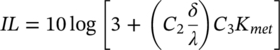
where C2 = 20 and includes the effect of ground reflections; C2 = 40 if ground reflections are taken into account elsewhere. C3 is a factor to take into account of a double diffraction or finite barrier effects, C3 = 1 for a single diffraction, δ = (rs + rr) − r0, and
(9.55)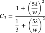
for double diffractions, δ = (rs + rr + w) − r0, where w is the width of the barrier.
When barriers are used outdoors in practice, they are inevitably affected by meteorological conditions which can substantially reduce barrier performance. The term Kmet in Eq. (9.54) is a correction factor for average downwind meteorological effects, and is given by
(9.56)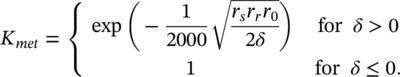
It can be seen that Eq. (9.54) reduces to the simple formula IL = 10 log(3 + 20 N) when the barrier is thin, there is no ground, and when meteorological effects are ignored. This formula is identical to that suggested by Tatge [122] and that derived from the empirical results of Maekawa [127] and depends only on the Fresnel number, N.
EXAMPLE 9.14
A long acoustical barrier of 1 m width and 4 m height is installed to reduce the noise of a source outdoors. The source and the receiver are both located 3 m above the ground and 6 m from the barrier, respectively. Estimate the insertion loss of the barrier in the 500‐Hz one‐octave band when the effect of ground reflections is included.
SOLUTION
The geometrical distances are:
![]() m,
m, ![]() m, r0 = 10 m, and w = 1 m. Then
m, r0 = 10 m, and w = 1 m. Then
δ = (rs + rr + w) − r0 = 5 + 7.2 + 1–10 = 3.2 m. The wavelength λ = c/f = 344/500 = 0.688 m.
Now, (5λ/w)2 = (3.44)2 = 11.83. We use C2 = 20 and ![]() .
.
The meteorological effect is determined as
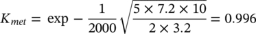 . Therefore,
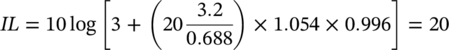 dB in the 500‐Hz octave band.
EXAMPLE 9.15
A noisy machine is located 30 m away from a receiver. A long and thin 2 m high barrier is placed 5 m from the machine to reduce the noise. The center of the machine is 0.5 m above the ground and the receiver is located 1.5 m above the ground. The machine produced a sound pressure level of 69.6 dB at the receiver position in the 250‐Hz one‐octave band without the barrier. Calculate the sound pressure level at the receiver with the barrier, ignoring meteorological effects. Consider that the ground between the machine and the receiver is soft, level, flat and unobstructed.
SOLUTION
We first calculate the geometrical distances involved in the problem:

Then, δ = 5.220 + 25.005–30.017 = 0.208 m. λ = 344/250 = 1.376 m, and

Since the ground is soft and the barrier is thin, we can use IL = 10log(3 + 20 N). Therefore,

Finally, the sound pressure at the receiver with the barrier is
Lp = Lp (without the barrier) − IL = 69.6 − 9.6 = 60 dB in the 250‐Hz octave band.
Other empirical charts, algorithms, and theories have been presented for predicting the noise attenuation provided by barriers [127–130]. References [116, 117] discuss some of these approaches.
Leave a Reply