The theoretical p−V diagram for single acting compressor is shown in Fig.12.4. The line 4–1 represents the suction stroke. The air is then compressed adiabatically as shown by the curve 1–2 in Fig. 12.4. It is then forced out of the cylinder at constant pressure p2, as shown by the line 2–3. The work done is represented by the area 1–2–3–4–1.
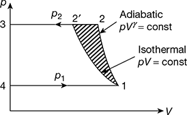
Figure 12.4 Theoretical p-V diagram for single acting compressor
If the air had been compressed isothermally, as represented by the curve 1–2′, then the work done on the air would be the area 1–2′–3–4–1, which is considerably less than that due to adiabatic compression. However, it is not possible in practice to compress the air isothermally because in that case, the compressor would need to run extremely slow. In practice, the compressors are driven at fairly high speeds in order to compress as much air as possible in a given time. Hence, the compression of air will approximate to an adiabatic. The work saved by compressing isothermally is shown by the shaded area 1–2–2′–1.
1 Methods for Approximating Compression Process to Isothermal
The following practical methods are used to achieve nearly isothermal compression:
- Cold water spray: In this method, cold water is sprayed onto the cylinder during compression, thus reducing the temperature of the air. Without the cold water spray, the compression would have been adiabatic or pVγ = constant. This effect is shown in Fig. 12.5, where now the compression would be between adiabatic and isothermal or pVn = const., where 1 < n < 1.4. The work saved is represented by 1-2-2′′-1.
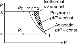 Figure 12.5 Effect of type of compression on work done.
 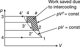 Figure 12.6 Multi-stage compression
 - Water jacketing: The water is circulated around the cylinder through the water jacket to cool the air during compression. This method is commonly used for all types of reciprocating compressors.
- Intercooling by using multi-stage compression: In a multi-stage compressor, the air is compressed in several stages. In principle, it is equivalent to number of compressors in series where the air passes from one cylinder to the next and the pressure increases in each cylinder. The p − V diagram for a four-stage compressor is shown in Fig. 12.6. The dotted line 1–4′ is the isothermal. In the first stage, the air is compressed adiabatically to 2′ and cooled at constant pressure to 2′ in the intercooler, possibly to the initial temperature. For complete intercooling, the point 2′ is on the isothermal line 1–4′. The air is then drawn into the second cylinder for the second stage of compression and the process is repeated for the subsequent cylinders. Line 1–a represents the adiabatic compression in a single cylinder. The compressor work saved by intercooling is represented by the area 2–a–4–3′–3–2′–2.
- External fins: Small capacity compressors are provided with fins to increase the heat transfer from the surface of the cylinder.
Leave a Reply