1 Efficiency
The Brayton cycle is shown on p-V and T-s diagrams in Fig. 16.4. During this cycle, air is drawn into the compressor at point 1 and then compressed isentropically along the process 1-2. Process 2-3 represents the burning of the oil at constant pressure p2. Process 3-4 is the isentropic expansion of the gases through the turbine. Process 4-1 represents the exhausting and cooling of the gases at constant pressure p1.
For 1 kg of air,
Compressor work, wc = w1−2 = h2 − h1 = cp (T2 − T1)
Heat supplied, q = q2−3 = h3 − `h2 = cp (T3 − T2)
Turbine work, wt = w3−4 = h3 − h4 = cp (T3 − T4)
Net work done, wnet = wt − wc = cp [(T3 − T4) − (T2 − T1)]
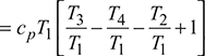
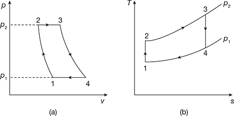
Figure 16.4 Brayton cycle for constant pressure gas turbine: (a) p-V diagrams, (b) T-s diagrams
Let ![]() be the pressure ratio and
be the pressure ratio and ![]()
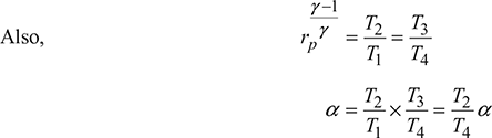
For the adiabatic compression process 1-2, we have
and for the adiabatic expansion process 3-4, we have
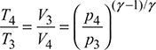
But p1 = p4 and p2 = p3
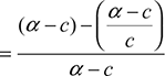
∴ ![]()
Thermal efficiency, ![]()
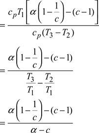
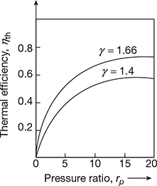
Figure 16.5 Variation of thermal efficiency with pressure ratio

The variation of thermal efficiency with rp is shown in Fig. 16.5.
2 Specific Output
Specific output ![]()

For maximum specific output, 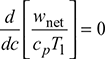

or 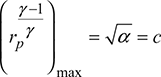
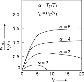
Figure 16.6 Variation of specific output with pressure ratio

Hence, for maximum work output, the temperature after compression must be equal to the exhaust gas temperature, which depends on the expansion ratio. The variation of specific output with rp is shown in Fig. 16.6.
3 Maximum Work Output
Maximum work output,
(wnet)max = cp [(T3 − T4) − (T2 − T1)]
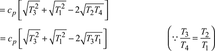
= cp [T3 + T1 − T4 − T2]


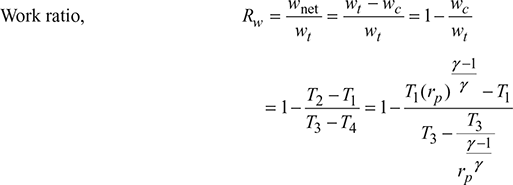
4 Work Ratio
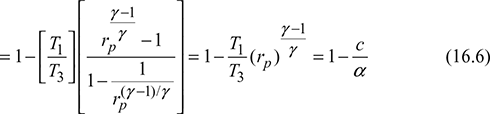
5 Optimum Pressure Ratio for Maximum Specific Work Output
wnet = wt − wc = cp (T3 − T4) − cp (T2 − T1)
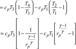
wnet will be maximum, when ![]()
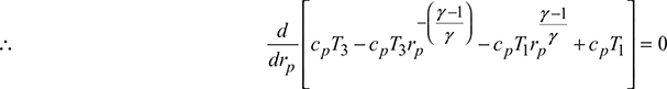
Let ![]()
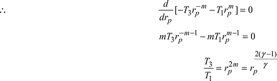

From Eq. (16.3), we have
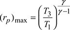
Combining with Eq. (16.7), we get

Leave a Reply