The thermodynamic wet bulb temperature or AST is the temperature at which the air can be brought to saturation state adiabatically by the evaporation of water in the flowing air. A schematic representation of this process, called the adiabatic saturation process, is shown in Fig. 20.3. It consists of an adiabatic enclosure containing adequate quantity of water. There is also an arrangement for feed water from the top.
The unsaturated air enters the enclosure at section 1. As the air flows through the enclosure water evaporates which is carried by the flowing stream of air. Thus the specific humidity of air increases. The water level in the enclosure is maintained by the feed water. Both the air and water are cooled as the evaporation takes place. The process continues until the energy transferred from the air to water is equal to the energy required to vaporise water. When steady conditions are reached, the air flowing at section 2 becomes saturated with water vapour. The temperature of the saturated air at section 2 is known as thermodynamic wet bulb temperature or adiabatic saturation temperature. The adiabatic saturation process is represented on T-s diagram as shown by the curve 1-2 in Fig. 20.4. The adiabatic saturation temperature is taken equal to the wet bulb temperature.
Let td1 = DBT of initial unsaturated air
td2 = DBT of saturated air
= adiabatic saturation temperature, tw
h1, h2 = enthalpy of unsaturated and saturated air respectively
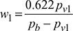
w1, w2 = specific humidity of air at sections 1 and 2 respectively
hfw = sensible heat of water at adiabatic saturation temperature
For energy balance of air at inlet and outlet, we have
h1 + (w2 − w1)hfw = h2
or h1 + whfw1 = h2 + whfw1
Now h1 = ha1 + w1 hs1
and h2 = ha2 + w2 hs2
where ha1 = enthalpy of 1 kg dry air at DBT = td1 = cpa td1
hs1 = enthalpy of superheated vapour at td1 per kg of vapour
ha2 = enthalpy of 1 kg dry air at WBT = tw = cpa td2
hs2 = enthalpy of saturated vapour at WBT = tw per kg of vapour
Thus, we get
(ha1 + w1hs1) − w1hfw = (ha2 + w2hs2) − w2hfw
w1(hs1 + hfw) = w2 (hs2 + hfw) + (ha2 − ha1)
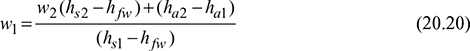
Also h1 = cpatd1 + w1hs1
h2 = cpatd2 + w2hs2
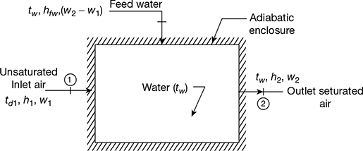
Figure 20.3 Adiabatic saturator
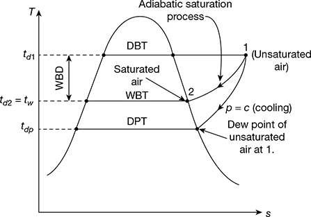
Figure 20.4 T-s diagram for adiabatic saturation process
where hs2 = hf2 + hfg2
hs1 = hs2 + cpv (td1 − td2) = hf2 + hfg2 + cpv (td1 − td2)
From the energy balance, we get
cpatd1 + w1[hf2 + hfg2 + cpv (td1 − td2)]+ (w2 − w1) hf2
= cpatd2 + w2 (hf2 + hfg2)
or (cpa + w1 cpv)td1 − (cpa + w2 cpv)td2 = hfg2 (w2 − w1)

where cp1 and cp2 are humid specific heats
If cp1 = cp2 = cp, then
cp (td1 − td2) = hfg2 (w2 − w1)

Example 20.4
Atmospheric air at 1 bar enters the adiabatic saturator. The dry bulb temperature is 30°C and wet bulb temperature 20°C during adiabatic saturation process. Calculate the following:
- Humidity ratio of entering air,
- Vapour pressure and relative humidity at 30°C, and
- Dew point temperature.
Solution
Given: pb = 1 bar, td = 30°C, tw = 20°C
- Saturation pressure of vapour at 20°C, from steam tables is,pv2 = 2.34 kPa or 0.0234 barEnthalpy of saturated vapour at 20°C, hs2 = hg2 = 2538.2 kJ/kgSensible heat of water at 20°C, hfw = 83.9 kJ/kgEnthalpy of saturated vapour at 30°C, hs1 = hg1 = 2556.4 kJ/kgEnthalpy of 1 kg unsaturated air at td = 30°C,ha1 =mcpatd =1×1.005×30 = 30.15kJ/kgEnthalpy of 1 kg saturated air at tw = 20°C,ha2 =mcpatw =1×1.005× 20 = 20.10 kJ/kg
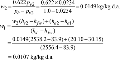
- Now
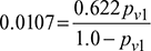 0.0107 − 0.0107 pv1 = 0.622 pv1pv1 = 0.0169 barSaturation pressure corresponding to 30°C from steam tables is,ps = 4.246 kPa or 0.04246 barRelative humidity,
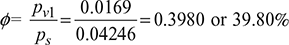
- Dew point temperature is the saturation temperature corresponding to the partial pressure of water vapour, pv1 = 0.0169 bar or 1.69 kPaFrom steam tables, we havetdp = 14.85°C
Leave a Reply