The arrangement are the same as constant mesh type gear box. Gears on the main shaft mesh with those on lay shaft. The gears on the lay shaft are fixed. This provision avoids the need for double declutching.
Figure 2.7 shows design of a synchromesh gear box. These devices reduce the cost.
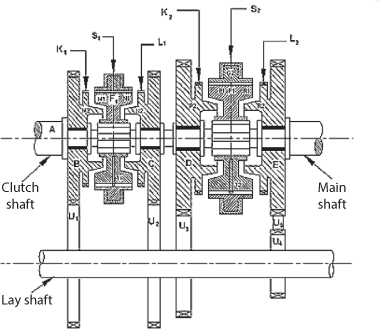
Gears B, C, D, E in Figure 2.7 are free to move on the main shaft and are in mesh with gears on the lay shaft. Menders F1 and F2 are free to move on splines on the main shaft. G1 and G2 have internal teeth fit onto the external teeth members F1 and F2 respectively. However, when the force applied in G1 (G2) through fork S1 (S2) exceeds a certain value, the balls are overcome and member G1 (G2) slides over F1 (F2).
For direct gear, member G1 and hence member F1 (through spring–loaded balls) is slid towards the left till comes M1 and M2 rub and friction makes their speed equal. For the second gear the members F1 and G1 are slid to the right so that finally the internal teeth on G1 are engaged with L1. Then the drive to main shaft will be from B via U1, U2, C, F1 and splines. For first gear, G2 and F2 are moved towards the right. In this case the drive will be from B via U1, U3, D, F2 and splines to the mainshaft. For reverse, G2 and F2 are slid towards the right. In this case the drive will be from B via, U1, U4, U5, D, F2 are splines to the main shaft.
Leave a Reply