The delivery pressure v’s mass flow rate in a dynamic compressor is shown in Fig. 14.13. Suppose a discharge valve is put in the line for this compressor. The mass rate of flow will be zero when the discharge valve is closed and the static pressure developed is that delivered by the impeller to the air contained in the compressor. Such a situation is shown by point a in Fig. 14.13. If the valve is now opened, the flow of air takes place and the diffuser becomes effective in increasing the static pressure. This is shown by points b and c. The maximum delivery pressure is obtained at point c. As the valve is opened more, the mass flow rate increases beyond point c and the efficiency of compressor decreases with decrease in delivery pressure. When the designed mass rate is greatly exceeded, the incidence between the vane and air angle becomes so large that flow separation and shock occur, accompanied by rapid decrease in efficiency.
If the compressor operates at some point b to the left of point c, then a decrease in mass rate of flow is accompanied by decrease in pressure developed by the compressor. If the static pressure of the air at compressor outlet does not decrease as rapidly as the developed pressure, there is a natural tendency of the air to flow back into the compressor in the direction of pressure gradient. With the drop in pressure at the compressor outlet, the pressure gradient is reversed and also the direction of flow is reversed. Thus, this leads to unstable condition of cyclic reversal taking place at extremely high frequencies. This pulsating air flow phenomena is called ‘surging’. Such a situation is avoided by keeping the operating point to the right of point c, because in this region a decrease in mass flow rate is accompanied by increase in delivery pressure, leading to stability.
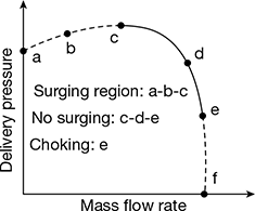
Figure 14.13 Surging and choking phenomena
After point c, any increase in mass flow rate is accompanied by decrease in delivery pressure. This happens because the rate of increase in pressure loss due to the friction is more than the rate of increase in pressure gain by diffuser. Theoretically, the decrease in delivery pressure is continued until the mass flow rate is represented by the point ‘f’. In practice, the maximum mass flow is limited by the point e because if the mass flow exceeds design mass flow, the air angles are widely different from vane angles and choking takes place. The point e represents the choking of the compressor, that is, the maximum mass flow rate condition.
Surging does not take place in the region ce as the reduction in mass flow rate is accompanied with the increase in delivery pressure and flow reversal is not possible and stability of operation is maintained.
Example 14.1
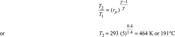
A centrifugal air compressor having a pressure ratio of 5, compresses air at a rate of 10 kg/s. If the initial pressure and temperature are 1 bar and 20°C respectively, find the final temperature of air and power required to drive the compressor. Take γ = 1.4 and cp = 1 kJ/kg.K.
Solution
Given: rp = 5, ṁ = 10 kg/s, p1 = 1 bar, T1 = 273 + 20 = 293 K, γ = 1.4, cp = 1 kJ/kg.K
Power required to drive the compressor,
P = ṁcp (T2 − T1) = 10 × 1 × (464 − 293) = 1710 kW.
Example 14.2
A centrifugal compressor has a pressure ratio of 4:1 with an isentropic efficiency of 82% when running at 16,000 rpm. It takes in air at 17°C. Guide vanes at inlet give the air a pre whirl of 20° to the axial direction at all radii and the mean diameter of the eye is 200 mm, the absolute air velocity at inlet is 120 m/s. At exit, the blades are radially inclined and the impeller tip diameter is 550 mm. Calculate the slip factor of the compressor.
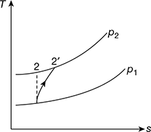
Figure 14.14 T – s Diagram
Solution
![]() = 4, T1 = 273 + 17 = 290 K, N = 16,000 rpm, α1 = 90° − 20° = 70°
= 4, T1 = 273 + 17 = 290 K, N = 16,000 rpm, α1 = 90° − 20° = 70°
d1 = 200 mm, va1= 120 m/s, ηisen = 0.82, d2 = 550 mm, β2 = 90°
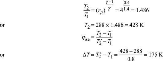
Temperature after isentropic compression (Fig. 14.14)
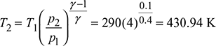
Isentropic temperature rise,
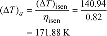
(∆T)isen = 430.94 – 390 = 140.94 K
Actual temperature rise,
Power input per unit mass flow rate
= cp × (∆T)a = 1.005 × 171.88 = 172.74 kJ/kg
An inlet to impeller (Fig. 14.15 (a)),
va1 = 120 m/s
Angle of pre-whirl = 20°
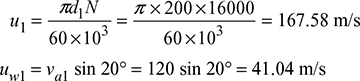
At exit of impeller (Fig. 14.15(b))
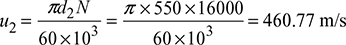
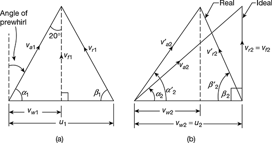
Figure 14.15 Velocity diagrams for centrifugal compressor: (a) Inlet, (b) Outlet
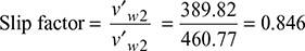
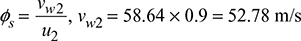
For radial discharge, vw2 = u2 = 460.77 m/s
Power input per unit mass flow rate
= u2v′w2 − u1vw1
= 460.77 v′w2 − 167.55 × 41.04 = 172.74 × 10³
v′w2 = 389.82 m/s
Example 14.3
A centrifugal compressor running at 15000 rpm takes in air at 15°C and compresses it through a pressure ratio of 4 with an isentropic efficiency of 80%. The blades are radially inclined and the slip factor is 0.85. Guide vanes at inlet give the air an angle of pre-whirl of 20° to the axial direction. The mean diameter of the impeller eye is 200 mm and the absolute air velocity at inlet is 120 m/s. Calculate the impeller tip diameter. Take cp = 1.005 kJ/kg.K and γ = 1.4.
Solution
Given: N = 15000 rpm, T1 = 273 + 15 = 288 K, rp = 4, ηisen = 80%, ϕs = 0.85, va1 = 120 m/s, d1 = 200 mm, α1 = 70°
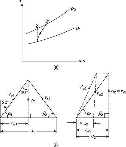
Figure 14.16 (a) T-s diagram, (b) Velocity triangles.
From Fig. 14.16 (a), we have
Compressor work, wc = cp · ∆T = 1.005 × 175 = 175.875 kJ/kg
From Fig. 14.16 (b), vw1 = va1 cos 70°
= 120 cos 70° = 41.04 m/s
For radial discharge, β2 = 90° and
vw2 = u2
Power input = u2![]() − u1 vw1
− u1 vw1
175·875 × 103 = u2 × 0.85 u2 − 157 × 41.04
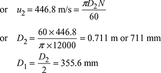
or u2 = 463.13 m/s
or d2 = 589.7 mm
Example 14.4
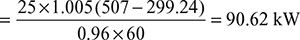
The free air delivered by a centrifugal compressor is 25 kg/min. The suction condition is 1 bar and 25°C. The velocity of air at inlet is 50 m/s. The isentropic efficiency of the compressor is 70%. If the total head pressure ratio of the compressor is 4, determine (a) the total head temperature of air at the exit of the compressor, and (b) brake power required to run the compressor assuming mechanical efficiency of 96%. Pressure and temperature of air at inlet are static. For air γ = 1.4 and R = 0.287 kJ/kg. K.
Solution
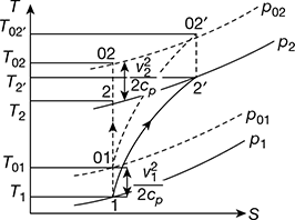
Figure 14.17 T–s diagram for centrifugal compressor
Refer to Fig. 14.17.
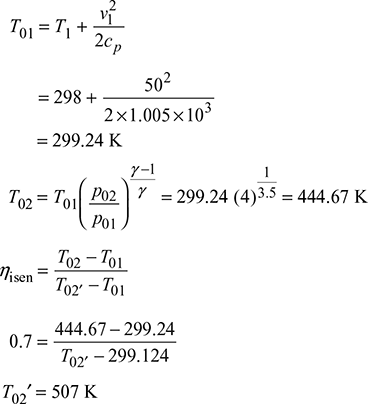
Brake power required to run the compressor = ![]()
Example 14.5
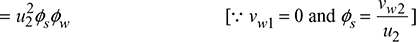
Air at a temperature of 20°C flows into the centrifugal compressor running at 21,000 rpm. The following data are given:
Slip factor = 0.85
Work input factor = 1.0
Isentropic efficiency = 72%
Outer diameter of blade tip = 60 cm
Assuming the absolute velocities of air entering and leaving the compressor are same, determine:
- Temperature rise of air passing through compressor, and
- Static pressure ratioTake cp = 1.005 kJ/kg. K.
Solution
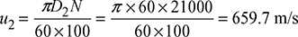
Work done per kg of air = u2vw2 − u1vw1
= (659.7)2 × 0.85 × 10−3 × 1 = 369.923 kJ/s
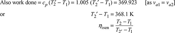
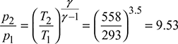
or T2 = 293 + 0.72 × 368.1 = 558 K
Static pressure ratio,
Example 14.6
A centrifugal compressor handles 180 kg/min of air. The suction pressure and temperature are 1 bar and 300 K. The suction velocity is 90 m/s. The delivery conditions are 2 bar, 400 K, and 240 m/s. Calculate (a) the isentropic efficiency, (b) the power required to drive the compressor, and (c) the overall efficiency of the unit. Take cp = 1.005 kJ/kg. K. Assume that entire kinetic energy gained in the impeller is converted into pressure in the diffuser.
Solution
![]() = 3 kg/s, p1 = 1 bar, T1 = 300 K, va1 = 90 m/s, p2 = 2 bar, T2 = 350 K, va2 = 240 m/s
= 3 kg/s, p1 = 1 bar, T1 = 300 K, va1 = 90 m/s, p2 = 2 bar, T2 = 350 K, va2 = 240 m/s
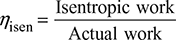
- Isentropic efficiency,
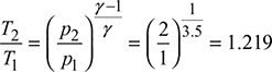 T2 = 300 × 1.219 = 365.7 KIsentropic work done, wisen = cp(T2 − T1) +
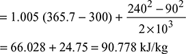 Actual work done in the impeller,
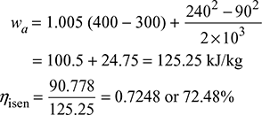
- Power required to drive the compressor = ṁ × wa = 3 × 125.25 = 375.75 kW
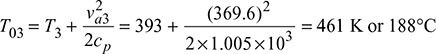
- Let T3 = temperature at the exit of diffuser
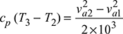 or 1.005 (T3 − 400) = 24.75or T3 = 424.6 K
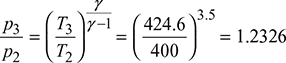 or p3 = 2 × 1.2326 = 2.465 barAfter isentropic compression, the delivery temperature from diffuser is,
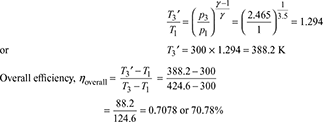
Example 14.7
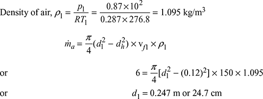
A centrifugal compressor handles 540 kg/min of air at 1 bar and 20°C ambient conditions. The air is compressed from 1 bar static pressure to 4.5 bar total pressure. The air enters the impeller eye with a velocity of 150 m/s with no pre-whirl. The ratio of whirl speed to tip speed is 0.9. Calculate (a) the rise in total temperature during compression if the change in kinetic energy is negligible, (b) the tip diameter of the impeller, (c) the power required, and (d) the eye diameter if the hub diameter is 130 mm.
Assume that the compressor runs to 20,000 rpm with isentropic efficiency of 82%.
Solution
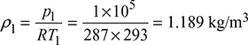
![]() = 9 kg/s, p01 = p1 = 1 bar, T1 = 273 + 20 = 293 K, N = 20,000 rpm, ηisen = 0.82,
= 9 kg/s, p01 = p1 = 1 bar, T1 = 273 + 20 = 293 K, N = 20,000 rpm, ηisen = 0.82,
p02 = 4.5 bar, va1 = 150 m/s, ![]() = 0.9, dh = 130 mm = 0.13 m
= 0.9, dh = 130 mm = 0.13 m
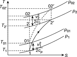
The T – s diagram is shown in Fig. 14.18.
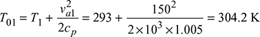
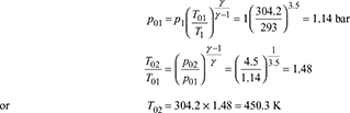 Isentropic rise in total temperature, (∆T)isen = 450.3 − 304.2 = 146.13 KActual rise in total temperature,
- Actual work consumed by the compressor, wactual = cp (∆T)actual = 1.005 × 178.2 = 179.1 kJ/kgWork consumed given by Euler’s equation without pre-whirl,
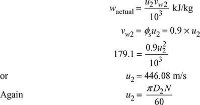 Tip diameter of impeller,
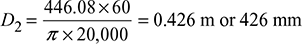
- Power required = ṁ × wactual = 9 × 179.1 = 1611.9 kW
 or D1 = 0.2848 m or 284.8 mm
Example 14.8
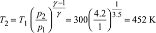
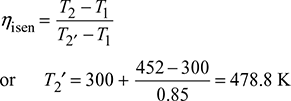
A centrifugal compressor delivers 720 m3/min of free air while running at 12,000 rpm. The ambient air conditions are 1 bar and 27°C. The air is compressed to 4.2 bar with an isentropic efficiency of 0.85. Blades are radial at the outlet of the impeller and the flow velocity is 60 m/s, which may be assumed constant throughout. The outer radius of impeller is twice the inner and the slip factor is 0.9. The blade area coefficient is 0.9 at inlet. Determine (a) the final temperature of air, (b) the theoretical power, (c) the inlet and outlet diameter of impeller, (d) the breadth of impeller at inlet, (e) the impeller blade angle at inlet, and (f) the diffuser blade angle at inlet.
Solution
p1 = 1 bar, T1 = 273 + 27 = 300 K, p2 = 4.2 bar, ηisen = 0.85, vf2 = 60 m/s, r2 = 2r1, ϕs = 0.9, kb = 0.9.
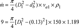
- Mass flow rate
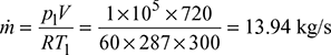 Theoretical power,
  = 13.94 × 1.005 (478.8 − 300) = 2504.4 kW
 - Work done =

- Volume flow rate = π D1b1kbvf1

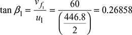 or β1= 15.03°
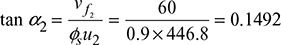 or α2 = 8.48°
Example 14.9
A centrifugal blower compresses 5.4 m3/s of air from 1 bar and 25°C to 1.5 bar. The index of compression is 1.5. The flow velocity of 70 m/s is constant throughout. The inlet and outlet diameters of impeller are 0.30 m and 0.60 m, respectively. The blower rotates at 9000 rpm. Determine (a) the blade angles at inlet and outlet of the impeller, (b) the absolute angle at the tip of the impeller, and (c) the breadth of blade at inlet and outlet.
Assume that no diffuser is employed and the whole pressure increase occurs in the impeller and the blades have negligible thickness.
Solution
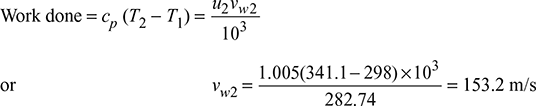
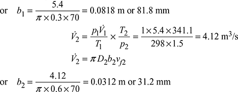
V̇1 = 5.4 m3/s, p1 = 1 bar, T1 = 273 + 25 = 298 K, n = 1.5, p2 = 1.5 bar, vf1 = vf2 = 70 m/s, D1 = 0.3 m, D2 = 0.6 m, N = 9000 rpm
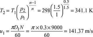
u2 = 2u1 = 282.74 m/s
Example 14.10
A centrifugal compressor delivers 18 kg/s of air with a total head pressure ratio of 4 : 1. The speed of the compressor is 16000 rpm. Total head temperature at inlet is 22°C, slip factor 0.9, power input factor 1.05 and isentropic efficiency 0.82. Calculate (a) the overall diameter of the impeller and (b) the power input.
Solution
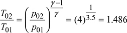
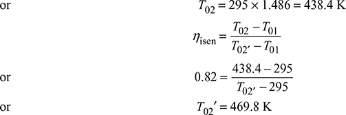
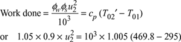
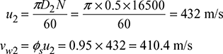
ṁ = 18 kg/s, rop = 4, N = 16000 rpm, T01 = 273 + 22 = 295 K, ϕs = 0.9, ϕw = 1.05, ηisen = 0.82
Example 14.11
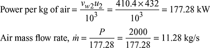
A single-sided centrifugal compressor impeller fitted with a diffuser, without water cooling, requires 2000 kW when running at 16,500 rpm. The outlet diameter of impeller is 0.5 m and the width of the casing of the vortex chamber between the impeller and the diffuser is 50 mm. During a test on this compressor, static temperature and pressure were measured at a radius of 0.28 m and were found to be 120°C and 3 bar, respectively. Assuming whirl speed at the tip of the impeller to be 0.95 of the peripheral speed and neglecting friction in vortex chamber, calculate (a) the flow rate, (b) the resultant speed at the section given, and (c) the total temperature at the section given. Take cp = 1.005 kJ/kg, K, γ = 1.4 and intake pressure = 1 bar.
Solution
P = 2000 kW, N = 16500 rpm, D2 = 0.5 m, b = 50 mm, ϕs = 0.95, p1 = 1 bar
- Work done = vw2u2
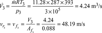
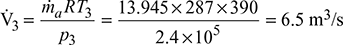
- Using suffix 3 for the given sectionArea of flow, Af 3 = 2πr3b3 = 2π × 0.28 × 50 × 10−3 = 0.088 m2Volume rate of flow at the given section,
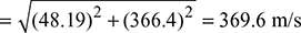
 For free vortex in vaneless space, vw1 × r1 = const.i.e., vw1r1 = vw2r2 = vw3r3
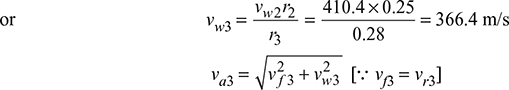
Example 14.12
A centrifugal compressor delivers 580 m3/min of free air when running at 8000 rpm. Use the following data: inlet pressure and temperature of air = 1.013 bar and 20°C, pressure ratio = 3.5, isentropic efficiency = 83 %, flow velocity throughout the compressor = 62 m/s, the blades are radial at the outlet of the impelier, tip diameter = 2 times eye diameter, blade area coefficient = 0.94. Find (a) the input power required to run the compressor, (b) the impeller diameters at inlet and outlet, (c) the breadth of impeller at inlet, and (d) the impeller blade angle at inlet.
Solution
Given that V̇a = 580 m3/min, N = 800 rpm, p1 = 1.013 bar, T1 = 273 + 20 = 293 K, rp = 3.5, ηisen = 0.83, vf = 62 m/s, β2 = 90°, D2 = 2D1, kt = 0.94
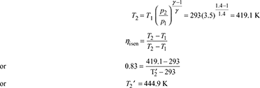
Mass flow rate of air, 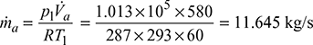
- Input power required
 = 1777.72 kW
 - For radial blades, work done on compressor,
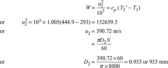
- V̇a = πD1b1vfktor
 = π × 0.4665 × b1 × 62 × 0.94or b = 0.113 m or 113 mm
 β1 = 17.6°
Example 14.13
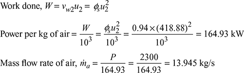
A centrifugal compressor runs at 16,000 rpm and 2300 kW of power is required to run the compressor. The outer diameter of the impeller is 50 cm. The uniform width of the casing of vortex chamber between impeller and diffuser is 4 cm. Static conditions at a radius of 27 cm were measured and it were equal to 2.4 bar and 390 K. Surrounding pressure is 1 bar. Assuming slip factor of 0.94, find (a) the mass flow rate of gas, (b) the resultant velocity and (c) the temperature at the given radius of 27 cm. Assume cp = 1.005 kJ/kgK and γ = 1.4.
Solution
Given that N = 16,000 rpm, P = 2300 kW, D2 = 50 cm, B = 4 cm, At R = 27 cm, p = 2.4 bar, T = 390 K, p1 = 1 bar, ϕs = 0.94, cp = 1.005 kJ/kg.K, γ = 1.4
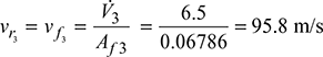
- Using suffix 3 for the given section,Area of flow, Af3 = 2πR3B3 = 2π × 0.27 × 0.04 = 0.06786 m2Volume rate of flow,
 For free vortex in vaneless space, vw1 × r1 = const.i.e., vw1r1 = vw2r2 = vw3r3
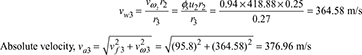
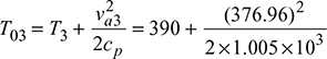 = 460.98 K = 461 K or 188°C
Example 14.14
A centrifugal compressor has to deliver 6kg/s of air with pressure ratio of 4:1 at 17500 rpm. Initial conditions are static air at 1 bar and 15°C. Assuming an adiabatic efficiency of 78%, ratio of whirl speed to tip speed 0.94 and neglecting all other losses, calculate the tip speed, diameter, and rise in total pressure. Determine the external diameter of eye for which the internal diameter is 12 cm and the axial velocity at inlet is 150 m/sec. Assume cp = 1.005 kJ/kgK and γ = 1.4.
Solution
Given that: ṁa = 6 kg/s, ![]() = 4, N = 17500 rpm, p01= 1 bar, T01 = 273 + 15 = 288 K, ηisen = 0.78,
= 4, N = 17500 rpm, p01= 1 bar, T01 = 273 + 15 = 288 K, ηisen = 0.78, ![]() = 0.94, dh = 12 cm, for radial inlet, α1 = 90° and vf1 = va1 = 150 m/s, cp = 1.005 kJ/kg.K, γ = 1.4
= 0.94, dh = 12 cm, for radial inlet, α1 = 90° and vf1 = va1 = 150 m/s, cp = 1.005 kJ/kg.K, γ = 1.4
The T-s diagram is shown in Fig. 14.19(a) and the impeller is shown in Fig. 14.19(b)
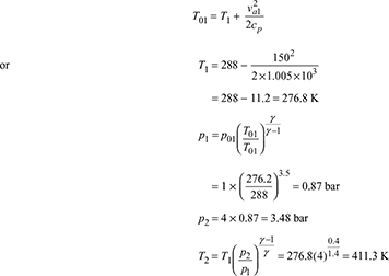
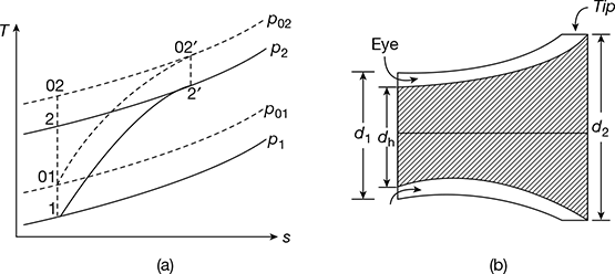
Figure 14.19 Diagrams for centrifugal compressor: (a) T-s diagram, (b) Impeller
Let va1 = va2, then
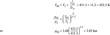
Rise in total pressure, ∆p0 = p02 − p01 = 3.82 – 1 = 2.82 bar
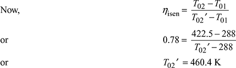
Work required per kg of air, w = cp(T02′ − T01)
= 1.005(460.4 − 288) = 173.262 kJ/kg
Also, work required per kg of air, ![]()
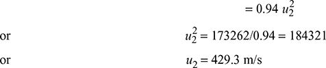
or d2 = 0.468 m or 46.8 cm
Example 14.15
A single-sided centrifugal air compressor delivers 1800 kg of air per minute. The air enters the eye of the impeller axially at total pressure of 100 kPa and total temperature of 290 K. The overall diameter of the impeller is 700 mm and it rotates at 1600 rpm. The slip factor is 0.9 and the work input factor is 1.1. The isentropic efficiency is 85%. Calculate (a) power required by the compressor, (b) pressure coefficient, and (c) total pressure at delivery.
[IES, 2003]
Solution
Given that ṁa = 1800 kg/min, α1 = 90, p01 = 100 kPa, T01 = 290 K, D2 = 700 mm, N = 1600 rpm, ϕs = 0.9, ϕw = 1.1, ηisen = 85%

- Pressure efficient, ϕp = ϕw ϕsηisen = 1.1 × 0.9 × 0.85 = 0.8415
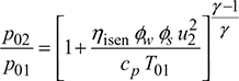
 or p02 = 100 × 1.00282 = 100.82 kPa
Example 14.16
A centrifugal compressor running at 18,000 rev/min takes in air at 25° C and compresses it through a pressure ratio of 4.0 with an isentropic efficiency of 80%. The guide vanes at inlet give the air an angle of pre-whirl of 20° to the axial direction. The mean diameter of impeller eye is 225 mm. The absolute air velocity at inlet is 130 m/s. At exit the blades are radially inclined. If the slip factor is 0.90, calculate the impeller tip diameter.
[IAS, 1999]
Solution
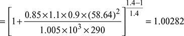
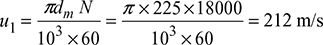
Given that N = 18000 rpm, T1 = 25 + 273 = 298 K, rp = 4, ηisen = 80%, pre-whirl at inlet = 20° or α1 = 90° − 20° = 70°, dm = 225 mm, va1 = 130 m/s, β2 = 90°, ϕs = 0.90
Temperature after isentropic compression,
Isentropic temperature rise,
(∆T)isen = T2 − T1 = 442.83 – 298 = 144.83 K
Actual temperature rise, ![]()
Power input per unit mass flow rate = cp × (∆T)act = 1.005 × 181 = 181.9 kJ/kg
The velocity diagrams are shown in Fig. 14.20
vw1 = va1 cos α1 = 130 cos 70° = 44.46 m/s
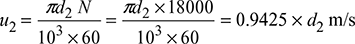
For radial discharge, vw2 = u2
Slip factor, ![]()
![]() = 0.9 vw2 = 0.9 × 0.9425 d2 = 0.84825 × d2 m/s
= 0.9 vw2 = 0.9 × 0.9425 d2 = 0.84825 × d2 m/s
Figure 14.20 Velocity diagrams: (a) Inlet, (b) Outlet
Power input per unit mass flow rate = u2 ![]() − u1 vw1
− u1 vw1
or 181.9 × 103 = 0.9425 × d2 × 0.84825 × d2 − 212 × 44.46
= 0.7995 ![]() − 9425.52
− 9425.52
or d2 = 488 mm
Example 14.17
A double-sided centrifugal compressor has root and tip diameters of 18 cm and 30 cm and is to deliver 16 kg of air per second at 16,000 rpm. The design ambient conditions are 15°C and 1 bar and the compressor has to be a part of a stationary power plant. Determine the following:
- Suitable values for impeller vane angles at the root and tip of the eye if the air is given 20° of pre-whirl at all radii. The axial component of the velocity is constant throughout the impeller and is 150 m/s.
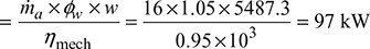
- Power required if the power input factor is 1.05 and mechanical efficiency is 95%
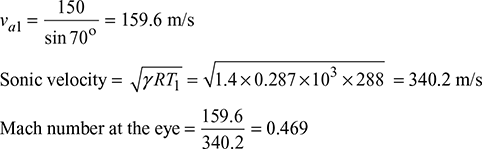
- Maximum Mach number at the eyeTake for air: cp = 1.005 kJ/kg K and γ = 1.4.
[IAS, 1998]
Solution
Given that r1 = 9 cm, r2 = 15cm, ṁa = 16 kg/s, N = 16000 rpm, T1 = 273 + 15 = 288 K
p1 = 1 bar, α1 = α2 = 70°, vf1 = vf2 = 150 m/s, ϕs = 1.05, ηmech = 95%, cp = 1.005 kJ/kg K, γ = 1.4
- Angular speed of rotor,
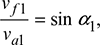
 The velocity diagrams are shown in Fig. 14.21.u1 = ωr1 = 1675.5 × 0.09 = 150.8 m/su2 = ωr2 = 1675.5 × 0.15 = 251.3 m/sα1 = 90° – angle of pre-whirl = 70°
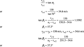
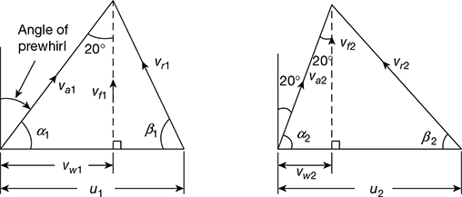 Figure 14.21 Velocity diagramsWork done per kg of air, w = vw2 u2 – vw1 u1 = vw1 (u1 − u1)= 54.6 (251.3 − 150.8) = 5487.3
 - Power required
Leave a Reply