Boilers are not always required to supply steam for economic or rated load but also required to meet the fluctuating demand of load, that is, peak fractional load. The boiler takes an appreciable time to change the rate of steam generation but the demand for a considerable change of power may occur instantly if the boiler could meet such a sudden increase in load; there is always the problem of disposing the steam once the peak has been passed. Moreover, in meeting the fluctuating load, the capacity and efficiency of boiler are reduced. To meet these requirements, it is a general practice to incorporate steam accumulators to equalise the load on the boilers. Thus, the steam accumulators acting as a thermal flywheel store energy during periods when the output of the boiler exceeds the demand and restores or supplies back the energy when the demand is more than the output of the boiler.
The steam accumulators are of two types, namely variable pressure system (Ruth’s accumulator) and constant pressure system (Kiesselbach accumulator).
1 Variable Pressure Accumulator
This accumulator (Fig. 3.32) was first introduced by Dr Ruth, a Swedish technician, in 1916. It consists of a steel shell filled with about 99% water under low pressure required by the low turbine or process work.
During charging, high pressure steam from the boiler enters the pipe C through the value V1. Under this condition, the non-return valve provided in pipe C is closed and the high pressure steam enters into the shell through the non-return valve B. Specially shaped nozzles surrounded by pipes are employed to discharge the steam silently into the water and thereby bring about condensation. This increases the pressure in the accumulator. The more the pressure rises in the accumulator, the greater becomes the thermal storage capacity.
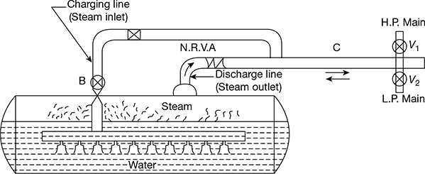
Figure 3.32 Ruth’s accumulator
During the discharging process (the demand of steam is more than output of boiler), the pressure in the pipe C falls below the pressure of water in the vessel when the low pressure mains valve is in communication with the industrial plant. In such circumstances, the pressure in the accumulator is also lowered, whereas the temperature remains same as before. This causes evaporation of water into steam, thereby increasing the pressure and reducing temperature until equilibrium condition between temperature and pressure is again attained. The non-return valve B is closed and steam passes to the low pressure turbine or industrial plant through the dome E and the non-return valve A. When the output of the steam equals the consumption of steam, there is no flow into and out of the accumulator.
Ruth’s accumulator gives a large discharge over a short period and a small discharge over a large period. This accumulator is widely used in mines and steel works where the reciprocating steam engines direct their intermittent exhausts into a low pressure receiver which is placed in series with accumulators. Low pressure turbines consume the steam supply from the accumulators.
The main advantages of this system are as follows:
- Increases the efficiency of boiler
- Increase in rate of evaporation, less repairs, and economy in fuel
- Rapid pick up
- Improvement in boiler load factor
2 Constant Pressure Accumulator
Figure 3.33 shows a constant pressure accumulator. This is used in conjunction with small water tube boilers, it stores heat in water during charging period (i.e., when the demand is less) but delivers water (not steam) during discharge period (i.e., when the demand is more than out-put). Therefore, this is essentially a feed-water accumulator.
In this system, the rate of firing of the boiler is maintained constant but the quantity of feed is varied. When there is fall in the demand for steam, an extra quantity of feed water is circulated through the boiler where the feed-water temperature rises to that of steam, and after that the surplus water is passed into the accumulator.
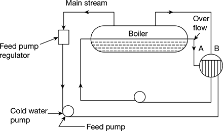
Figure 3.33 Kiesselbach accumulator
Leave a Reply