The sound radiation from plates and cylinders in bending (flexural) vibration is discussed in Refs. [9, 27] and chapter 10 in the Handbook of Acoustics [1]. There are interesting phenomena observed with free‐bending waves. Unlike sound waves, these are dispersive and travel faster at higher frequency. The bending‐wave speed is cb = (ωκcl)1/2, where κ is the radius of gyration h/(12)1/2 for a rectangular cross‐section, h is the thickness, and cL is the longitudinal wave speed {E/[ρ(1 − σ2)]}1/2, where E is Young’s modulus of elasticity, ρ is the material density, and σ is Poisson’s ratio. When the bending‐wave speed equals the speed of sound in air, the frequency is called the critical frequency (see Figure 3.24). The critical frequency is
(3.85)![]()
Above this frequency, fc, the coincidence effect is observed because the bending wavelength λb is greater than the wavelength in air λ (Figure 3.25), and trace wave matching always occurs for the sound waves in air at some angle of incidence (see Figure 3.26). This has important consequences for the sound radiation from structures and also for the sound transmitted through the structures from one air space to the other (see Chapter 12 of this book).
For free‐bending waves on infinite plates above the critical frequency, the plate radiates efficiently, while below this frequency (theoretically) the plate cannot radiate any sound energy at all [27]. For finite plates, reflection of the bending waves at the edges of the plates causes standing waves that allow radiation (although inefficient) from the plate corners or edges even below the critical frequency. In the plate center, radiation from adjacent quarter‐wave areas cancels. But radiation from the plate corners and edges, which are normally separated sufficiently in acoustic wavelengths, does not cancel. At very low frequency, sound is radiated mostly by corner modes, then up to the critical frequency, mostly by edge modes. Above the critical frequency the radiation is caused by surface modes with which the whole plate radiates efficiently (see Figure 3.27). Radiation from bending waves in plates and cylinders is discussed in detail in Refs. [9, 27] and chapter 10 of the Handbook of Acoustics [1]. Figure 3.28 shows some comparisons between theory and experiment for the level of the radiation efficiencies for sound radiation for several practical cases of simply-supported and clamped panel structures with acoustical and point mechanical excitation.
EXAMPLE 3.15
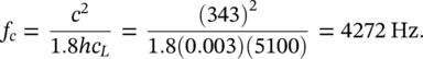
Determine the critical frequency for a 3 mm thick steel plate.
SOLUTION
The longitudinal wave speed in aluminum is cL = 5100 m/s. Now, replacing κ = h/(12)1/2 in Eq. (3.85) yields
Sound transmission through structures is discussed in Chapter 12 of this book and chapters 66, 76, and 77 of the Handbook of Acoustics [1].
Figure 3.29a and b show the logarithmic value of the radiation efficiency 10log σ plotted against frequency for stiffened and unstiffened plates. See Ref. [27] for further discussion on the radiation efficiency σrad, which is also known as radiation ratio.
Leave a Reply