The theory of vibration isolation presented in Chapter 2 shows that in order to reduce the magnitude of the force transmitted by an isolator to its support, one has to choose its natural frequency, fn, so that the ratio of the forcing frequency to the natural frequency, (f/fn) is much greater than ![]() . This means that for most air‐conditioning and ventilating equipment operating in a general range of 500 to 1800 rpm (i.e. 8–30 Hz), efficient vibration isolators should have a natural frequency well below this range. Such a low natural frequency requires a large static deflection, which in such cases may be of the order of 0.5–5 cm (0.25–2 in.).
. This means that for most air‐conditioning and ventilating equipment operating in a general range of 500 to 1800 rpm (i.e. 8–30 Hz), efficient vibration isolators should have a natural frequency well below this range. Such a low natural frequency requires a large static deflection, which in such cases may be of the order of 0.5–5 cm (0.25–2 in.).
In describing practical vibration isolators, the following parameters are often used:
(13.7)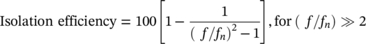
and
(13.8)![]()
for d = static deflection in centimetres, or
(13.9)![]()
for d = static deflection in inches.
The natural frequency in cycles per minute would clearly be fn × 60.
Figure 13.35 shows the relationship between f, fn, d, and efficiency for a linear one‐degree‐of‐freedom mass‐spring‐isolator system.
EXAMPLE 13.5
Various items of equipment each of 500 kg mass are operated at 600, 1200 and 1800 rpm. Determine the natural frequency fn and isolation efficiency achieved at each of the three operating conditions for isolators which produce static deflections of 0.5 cm (0.2 in.), 1.0 cm (0.5 in.), 2.5 cm (1.0 in.) and 5 cm (2.0 in.).
SOLUTION
The natural frequency is unchanged by the operating rpm of each machine. The natural frequency and isolation efficiency are determined for each operating condition using Eq. (13.7) and Eq. (13.8), and are given in Table 13.7.
EXAMPLE 13.6
Spring isolators normally have small damping but are durable with well‐defined performance. Figure 13.35 provides the performance of isolators, in which damping is neglected. Calculate the properties of a spring isolation system to achieve 95% isolation efficiency using Figure 13.35 for a disturbing frequency of (a) 600 rpm and (b) 1200 rpm.
SOLUTION
- For 600 rpm (10 Hz), Figure 13.35 gives a static deflection d = 5.0 cm (2 in.) for an isolation efficiency of 95% and a natural frequency fn of 130 rpm (2.17 Hz).
- For 1200 rpm (20 Hz), d = 1.3 cm (0.5 in.) and fn = 260 rpm (4.3 Hz).
Although there are no exact criteria for the minimum isolation efficiency, one should attempt to choose an isolator providing the maximum possible isolation efficiency for practical conditions of static deflection, stability, and vibration amplitude. Generally, values in excess of 90% are adequate.
The nature of the exciting force should first be determined to see whether it is periodic or impulsive. If it is impulsive, then a different approach is required. However, in mechanical rooms, the exciting forces are almost certain to be random or periodic in nature and may arise from a variety of sources including rotor imbalance or wear, pressure fluctuations, and turbulence in fan housings or in combustion processes. Unbalanced forces vary as the square of the speed and so can easily become intolerable.
Equipment isolators with natural frequencies close to the floor resonance frequency should be strictly avoided, and hence some estimate of the floor resonance frequency should be made at the outset of any isolator selection. As the floor span increases, its deflection also increases; hence, isolators used on large span floors require high static deflections so that their natural frequencies do not coincide with the floor resonances. Table 13.8 shows recommended isolator static deflections for a variety of mechanical room equipment operating at various speeds on several concrete floors with spans ranging from 6 to 18 m (20 to 50 ft). Isolators should be selected not only to have adequate vibration isolation efficiency but also to compensate for floor flexibility [20]. Longer floor spans are more flexible and more prone to vibration. Table 13.8 shows how isolators can be selected with consideration of equipment operating speeds and power as well as floor span. By specifying isolator deflections rather than isolation efficiency, the design engineer can compensate for floor stiffness by selecting isolators with greater deflection than the supporting floor [20].
Table 13.8 Recommended minimum static deflections for vibration isolators used with a variant of mechanical room equipment.
| Type of equipment | Noncritical locations | Critical location | |||||||||
|---|---|---|---|---|---|---|---|---|---|---|---|
| Basement below grade | 20‐ft (6.1 m) floor span | 30‐ft (9.15 m) floor span | 40‐ft (12.2 m) floor span | 50‐ft (15.2 m) floor span | |||||||
| mm | in. | mm | in. | mm | in. | mm | in. | mm | in. | ||
| Centrifugal fans and high‐pressure package units | |||||||||||
| Floor‐mounted units | Up to 20 hp | ||||||||||
| 175 to 300 rpm | 8.9 | 0.35 | 63.5 | 2.5 | 63.5 | 2.5 | 88.9 | 3.5 | 127 | 5.0 | |
| 301 to 500 rpm | 8.9 | 0.35 | 44.45 | 1.75 | 44.45 | 1.75 | 63.5 | 2.5 | 88.9 | 3.5 | |
| Above 500 rpm | 8.9 | 0.35 | 25.4 | 1.0 | 25.4 | 1.0 | 44.45 | 1.75 | 63.5 | 2.5 | |
| Above 20 hp | |||||||||||
| 175 to 300 rpm | 8.9 | 0.35 | 63.5 | 2.5 | 88.9 | 3.5 | 127 | 5.0 | 139.7 | 5.5 | |
| 301 to 500 rpm | 8.9 | 0.35 | 44.45 | 1.75 | 63.5 | 2.5 | 88.9 | 3.5 | 127 | 5.0 | |
| Above 500 rpm | 8.9 | 0.35 | 25.4 | 1.0 | 44.45 | 1.75 | 63.5 | 2.5 | 88.9 | 3.5 | |
| Vent sets and low‐pressure package units | |||||||||||
| Suspended units | Up to 5 hp | 19.05 | 0.75 | 25.4 | 1.0 | 25.4 | 1.0 | 25.4 | 1.0 | 25.4 | 1.0 |
| Above 5 hp | |||||||||||
| 175 to 500 rpm | 31.75 | 1.25 | 31.75 | 1.25 | 31.75 | 1.25 | 44.45 | 1.75 | 63.5 | 2.5 | |
| Above 500 rpm | 25.4 | 1.0 | 25.4 | 1.0 | 25.4 | 1.0 | 31.75 | 1.25 | 43.2 | 1.7 | |
| Floor‐mounted units | Up to 5 hp | 8.9 | 0.35 | 25.4 | 1.0 | 25.4 | 1.0 | 25.4 | 1.0 | 25.4 | 1.0 |
| Above 5 hp | |||||||||||
| 175 to 500 rpm | 8.9 | 0.35 | 44.45 | 1.75 | 44.45 | 1.75 | 44.45 | 1.75 | 63.5 | 2.5 | |
| Above 500 rpm | 8.9 | 0.35 | 25.4 | 1.0 | 25.4 | 1.0 | 38.1 | 1.5 | 43.2 | 1.7 | |
| Pumps | |||||||||||
| Close coupled | Up to 5 hp | 8.9 | 0.35 | 8.9 | 0.35 | 25.4 | 1.0 | 25.4 | 1.0 | 25.4 | 1.0 |
| Above 5 hp | 19.05 | 0.75 | 25.4 | 1.0 | 38.1 | 1.5 | 63.5 | 2.5 | 63.5 | 2.5 | |
| Base coupled | — | — | — | — | — | — | — | — | — | — | — |
| Refrigeration machines and boilers | |||||||||||
| Reciprocating air or refrigeration compressors | 500 to 750 rpm | 25.4 | 1.0 | 38.1 | 1.5 | 63.5 | 2.5 | 69.9 | 2.75 | 88.9 | 3.5 |
| Above 750 rpm | 25.4 | 1.0 | 25.4 | 1.0 | 38.1 | 1.5 | 63.5 | 2.5 | 68.6 | 2.7 | |
| Reciprocating chillers or heat pumps | 500 to 750 rpm | 25.4 | 1.0 | 38.1 | 1.5 | 63.5 | 2.5 | 69.9 | 2.75 | 88.9 | 3.5 |
| Above 750 rpm | 25.4 | 1.0 | 25.4 | 1.0 | 38.1 | 1.5 | 63.5 | 2.5 | 68.6 | 2.7 | |
| Package boiler units | — | 6.35 | 0.25 | 6.35 | 0.25 | 25.4 | 1.0 | 44.45 | 1.75 | 68.6 | 2.7 |
Typical vibration amplitudes and vibration severity curves are shown in Figure 13.36 for various steady machine speeds (in rpm). However, while the machine is being started or stopped, much larger amplitudes may occur as the machine speed (and hence the related forcing frequency) momentarily passes through and coincides with the isolator system’s natural frequency. For this reason, the isolator should have sufficient internal damping to keep the displacement within an acceptable limit at such resonances. It is also necessary to ensure that all connections (piping, wiring, and ducts) to the isolated equipment allow the machine to move at least 0.3 cm (0.1 in.) and that they have much less stiffness than the equipment isolators [24].
The vibration displacement of a machine mounted on isolators of adequate flexibility is independent of the isolator’s static deflection. Furthermore, the displacement can be significantly reduced by adding a massive concrete inertia base to the equipment. Inertia blocks are usually required for fans giving static pressures in excess of 9.0 cm (3.5 in.) of water or having a mechanical power greater than 40 HP and for base‐mounted pumps of over 10 HP. The base should have a weight at least 1.5–3 times the weight of the fan or compressor mounted on it.
The addition of an inertia base also lowers the center of gravity of the isolated equipment and in doing so helps to decouple the horizontal and rotational modes of vibration. The extra specification that each isolator shall have equal horizontal and vertical stiffnesses (iso‐stiff) also helps to decouple these modes. If they were well coupled, the result would be a rocking motion (rotation about the center of gravity) which, apart from being objectionable for the satisfactory performance of the equipment, might very well lead to failure. In order to achieve complete decoupling, the following conditions must be met:
- The center of gravity of the base of the equipment must be on the same horizontal plane as the isolators. This can be achieved only by using a T‐shaped inertia block.
- Each isolator should be iso‐stiff.
- The spacing between the isolators must be twice the radius of gyration of the system.
When mode coupling is considered, it is generally found that isolators have at least one natural frequency (either horizontal or rotational) greater than the vertical natural frequency [27].
Consequently, in order to avoid resonance and ensure low transmissibility, all these natural frequencies should fall below the limit imposed by the forcing frequency. This results in an even greater static deflection being required than if mode coupling were not considered. The greater static deflection is provided by softer isolators. The consequent reduction in vertical and horizontal stiffness, hence, further increases the possibility of isolator instability. This possibility can be reduced by decoupling the isolator modes as described above. Figure 13.37 shows the mounting of some commonly used vibration‐isolated inertia bases on a floating floor, as might be found in a ventilation mechanical room in a modern building.
Rooftop mounted mechanical systems require special attention to avoid structural transmission of vibration and noise. Figure 13.38 shows how a roof should be stiffened and a housekeeping pad (inertia base) added to reduce machine vibration for roof‐mounted equipment. Columns placed immediately below the equipment can minimize vibration transmitted through the building and in particular to noise‐sensitive occupied spaces below.
In cases where large static or dynamic horizontal forces may be present (i.e. in the case of a fan producing a water pressure of 15 cm (6 in.), some restriction must be placed on the horizontal movement of the inertia base. This is done with horizontal vibration isolators positioned so as to be in compression under load. When extreme movement has to be prevented, concrete or steel snubbers are often incorporated. Control of horizontal motion is of particular importance for equipment mounted in moving vehicles since sudden impacts could easily knock the equipment off its vibration mounts, with disastrous results! A commonly used method for controlling and restraining horizontal motion is shown in Figure 13.39.
In selecting a particular resilient material for use in a vibration isolator, many factors have to be considered. The foremost requirement is being able to achieve the desired static deflection. Other factors of considerable importance include cost, mechanical, and chemical stability, internal damping, linearity, size, and shape. Internal damping is necessary to reduce the vibration amplitude at resonance (i.e. during start‐up or shutdown), but it results in less isolation in the operating region. It is partly for this reason that steel spring isolators, which have very little internal damping, are usually equipped with or rested on a rubber or neoprene base. This has the added advantage of reducing the effect of standing wave resonances set up in the spring at frequencies where the spring height is an integral number of half‐wavelengths. These resonances often occur in the mid‐speech frequency range and appear as successive peaks in the isolator transmissibility curve. The heights of the resonance peaks are found to decrease with increasing forcing frequency, and for the resonances to disappear entirely at high frequencies (Figure 13.40). The addition of a rubber pad to a spring isolator thus increases its damping and noise isolation characteristics.
Another important consideration in the selection of an isolator material is the ease and accuracy with which its natural frequency and transmissibility can be calculated. In this respect, steel springs are superior since both the natural frequency and transmissibility can be easily and accurately predicted. On the other hand, it is fairly difficult to perform an equivalent calculation for rubber or neoprene. This is mainly due to the fact that the dynamic modulus of rubber is greater than its static modulus, although this depends upon the hardness of the material. Nevertheless, rubber and neoprene have several special advantages over steel springs and other resilient materials which make them particularly useful for many applications. The advantages and disadvantages of several commonly used resilient materials employed in vibration isolators are compared in Table 13.9 [27].
Table 13.9 Comparison of material used for vibration isolators [27].
| Material | Advantages | Disadvantages |
|---|---|---|
| Rubber | Easily molded and bonded to metal for easy attachment to equipmentRelatively good internal dampingGood for shock isolation because of its great energy storage capacityCan be used in compression and shear; combinations of these result in a wide range of characteristics to suit many needsCan be designed to have a constant natural frequency independent of load once in working region. | Cannot withstand strain for long periods or else creep will set in; usually limits of 10% in compression and 35% in shear are applicableCannot withstand very long or high temperaturesCannot be used in tension or else will failExtremely difficult to predict characteristicsIt is compressible thus requiring room to bulge outwards under compressionUseful only for static deflections less than 0.5 cm (0.2 in.). |
| Steel springs | Almost unlimited life, even under large stress, without drift or creepEasily designed to give required characteristics of natural frequency and stiffness (in both directions)Can be loaded in tension without failure, although almost always used in compressionLarge static deflections can be obtained, hence used mainly for low‐frequency isolation. | Low internal damping resulting in large amplitude at resonancePossibility of instability, especially if static deflection is large or lateral stiffness too smallUsually requires steel housingInternal resonances may be set up in spring. |
| Cork | Useful under concrete foundations; since it can cover the entire area, it simplifies the pouring of concreteIt is compressible and hence does not need room to bulge, unlike rubberHigh internal damping. | Very limited flexibility, hence rarely used to isolate primary vibrations. |
In general, steel springs should be used when static deflections in excess of 1.25 cm (0.5 in.) are required; while rubber isolators should be used for static deflections of less than 0.5 cm (0.2 in.).
When selecting a spring isolator, it is very important to check that the spring will not be overstressed or unstable when installed under the desired load. Such a system is assumed stable when the following condition is met:
(13.10)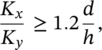
where Kx and Ky = stiffnesses of the spring in the horizontal and vertical directions, respectively; d = static deflection (vertical); and h = working height.
For the previously stated reasons, one usually requires a spring to be iso‐stiff, and in order for such a spring to be stable, the static deflection should be less than 80% of the working height. A static deflection of 0.3–0.6 of the working height should be the design objective. In order to prevent dynamic spring fatigue, helical springs should be precompressed and should not be used in circumstances where the shear stress would exceed 620 000 kPa (90 000 psi) at full static deflection for hot coiled springs of wire diameter greater than 0.5 cm (0.2 in.)
Leave a Reply