It is defined as the ratio of room sensible heat to the total heat (Fig. 20.29).

where RSH, RLH, RTH = room sensible, latent and total heats respectively.
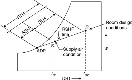
Figure 20.29 Room and supply air conditions and ADP
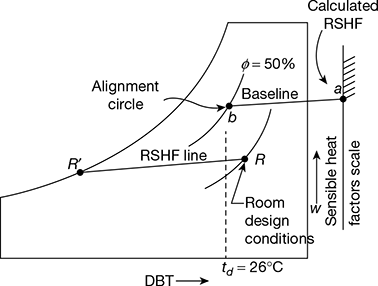
Figure 20.30 Grand sensible heat factor
1 Estimation of Supply Air Conditions
When the supply air conditions are not known, then the RSHF line may be drawn from the RSHF calculated value, as described below (Fig. 20.30).
- Mark point ‘a’ on the sensible heat factor scale drawn on the right hand corner of psychrometric chart. The point ‘a’ represents the calculated value of RSHF.
- Joint point ‘a’ with the alignment circle or reference point b (td − 26°C, ϕ = 50%). The line ab is called the base line.
- Mark point R on the psychrometric chart to represent the room design conditions.
- Draw a line RR’ through point R parallel to the base line ab. This line is required RSHF line.
Leave a Reply