The expansion of steam through a number of stages of turbine is shown in Fig. 7.13. A1B1 represents isentropic expansion in the first stage. The actual state of steam with frictional reheating is shown by point A2. Therefore, the actual heat drop in the first stage is A1C1. Similarly, the isentropic and actual heat drops in the succeeding stages are shown by A2B2, A3B3, ….., A2C2, A3C3, ….., and so on. A1D represents the isentropic heat drop between supply and condenser state of steam.
Stage efficiency, ![]()
For first stage, ![]()
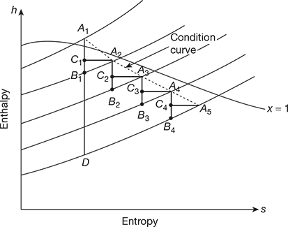
Figure 7.13 Expansion of steam through a number of turbine stages
For second stage, ![]() and so on.
and so on.


Turbine internal efficiency ![]()

If ηs1 = ηs2 = ….. = ηs′ then


From Eqs. (7.34) and (7.35), we get

Combining Eqs (7.33) and (7.36), we get
ηi = ηsRf
Reheat factor is always greater than one. Normally Rf lies between 1.02 to 1.05. The line passing through A1, A2, … is called the condition curve.
Leave a Reply