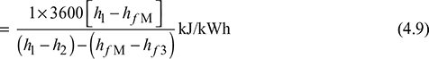
The schematic of Rankine cycle is shown in Fig. 4.3(a). It consists of a turbine, boiler, condenser, and pump. The p-v diagram is shown in Fig. 4.3(b) and the T-s diagram in Fig. 4.3(c). The delivery of steam from the boiler takes place at state 1 when assumed dry saturated or 1′ when assumed superheated. The steam expands isentropically in the prime mover to state point 2 from point 1 and 2′ from 1′.
After doing work at point 2 or 2′, the steam is condensed in the condenser to saturated water, represented by point 3 at pressure p2. This water is compressed isentropically to pressure p2 by the pump represented by the process 3−M. Thus, the boiler receives water at pressure p1 in a sub-cooled state, heats it to temperature corresponding to point 4, and further transforms it into steam at constant pressure p1. M−4−1 is the operation carried out in the boiler for dry saturated steam and M−4−1′ for superheated steam. All processes except the process of mixing of cold water at point M with hot water at point 4 are reversible. However, when we consider the flow of constant mass, this process gets deleted. The cycle begins again at 1 or 1′.
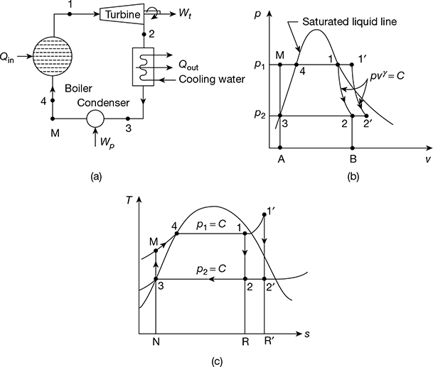
Figure 4.3 Rankine cycle: (a) Schematic diagram, (b) p-v diagram, (c) T-s diagram
1 Analysis of Rankine Cycle
Let h1 = enthalpy of steam at point 1
h2 = enthalpy of steam at point 2
hf3 = enthalpy of water at point 3
hf4 = enthalpy of water at point 4
hfM = enthalpy of water at point M
Heat added at constant pressure p1 represented by M−4−1,
qa = h1 − hfM = (h1 − hf3) − (hfM − hf3)
= area N−M−4−1−R−N on T-s diagram
Heat rejected at constant pressure p2 represented by 2−3,
qr = h2 − hf3
= area R−2−3−N−R on T-s diagram
Net work done, wnet = qa − qr
= (h1 − hfM) − (h2 − hf3)
= area 1−2−3−M−4−1
Pump work, wp = hfM − hf3
wnet = (h1 − h2) − wp
qa = (h1 − hf3) − wp
Now wp = 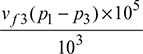 = vf3 (p1 − p3) × 102 kJ/kg, where p is in bar.
= vf3 (p1 − p2) × 102 kJ/kg
Thermal efficiency, ![]()

Neglecting pump work, which is small as compared to other quantities.


Overall heat rate (OHR) = Specific steam consumption × heat supplied per kg of throttle steam

Example 4.2
In an ideal Rankine cycle, saturated steam vapours enter the turbine at 160 bar and saturated liquid exits the condenser at 0.05 bar. The net power output of the cycle is 130 MW. Determine for the cycle (a) the thermal efficiency, (b) the steam mass flow rate, and (c) the specific steam consumption.
Solution
The Rankine cycle is shown in Fig. 4.4.
From steam tables,
For p1 = 160 bar, h1 = hg = 2580.6 kJ/kg, s1 = sg1 = 5.2454 kJ/kg.K
p2 = 0.05 bar, vf3 = 0.001005 m3/kg, vg3 = 28.193 m3/kg, hf3 = 137.79 kJ/kg,
hfg3 = 2423.7 kJ/kg, sf3 = 0.4763 kJ/kg.K, sfg3 = 7.9187 kJ/kg.K
For insentropic process 1−2,
s1 = s2 = sf3 + x2sfg3
or 5.2454 = 0.4763 + x2 × 7.9187
or x2 = 0.602
h2 = hf3 + x2hfg3 = 137.79 + 0.602 × 2423.7 = 1596.86 kJ/kg
h3 = hf3 = 137.79 kJ/kg
hM = h3 + vf3 (p1 − p2) × 102
= 137.79 + 0.001005 (160 − 0.05) × 102 = 153.86 kJ/kg
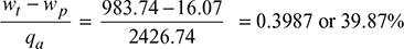
Turbine work, wt = h1 − h2 = 2580.6 − 1596.86 = 983.74 kJ/kg
Pump work, wp = hM − h3 = 153.86 − 137.79 = 16.07 kJ/kg
Heat added qa = h1 − hM = 2580.6 − 153.86 = 2426.74 kJ/kg
- Thermal efficiency =
- Steam mass flow rate,
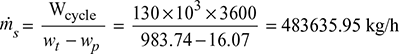
- Specific steam consumption,
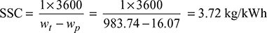
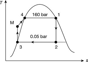
Figure 4.4 Ideal Rankine cycle
Example 4.3
In a steam power plant working on ideal Rankine cycle, the steam turbine receives steam at 10 bar 250°C and discharges at 0.5 bar. Find the thermal efficiency.
Solution
At p1 = 10 bar, ts = 179.91°C. Therefore, steam is superheated. The T-s diagram is shown in Fig. 4.5.
Figure 4.5 Rankine cycle
From steam tables, at 10 bar, 250°C,
h′1 = 2942.6 kJ/kg, s′1 = 6.9246 kJ/kg.K
At p2 = 0.5 bar, vf3 = 0.001030 m3/kg, hf3 = 340.47 kJ/kg, hfg3 = 2305.4 kJ/kg, sf 3 = 1.091 kJ/kg.K,
sfg3 = 6.5029 kJ/kg.K,
or 6.9246 = 1.091 + x′2 × 6.5029
or x′2 = 0.897

Pump work, wp = vf3 (p1−p2) × 102 = 0.001030 (10 − 0.5) × 102 = 0.9785 kJ/kg
Net work output ![]()
= (2942.6 − 2408.4) − 0.9785 = 533.22 kJ/kg
Heat added ![]()
Thermal efficiency ![]()
2 Effect of Boiler and Condenser Pressure
The Rankine cycle comprises internally reversible processes. Thus, the equation for thermal efficiency can be written in terms of average temperatures of heat addition and heat rejection processes.
With reference to Fig. 4.6, we have
Heat addition, qa = area 1−b−c−M−4−1
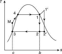
Figure 4.6 Heat addition and rejection in a Rankine cycle
Heat rejected, qr = area 2−b−c−3−2
= (Tavg)out (s2 − s3)
= (Tavg)out (s1 − sM)

Thus ηth increases if Tout decreases or Tin increases. Therefore, Eq. (4.11) can be used to study the effects on the performance of the changes in boiler and condenser pressures.
- Effect of boiler pressure: Consider two different cases having same condenser pressure but different boiler pressures as shown in Fig. 4.7(a). The average temperature of heat addition is higher for higher pressure cycle 1′-2′-3-M′-1′ than for cycle 1-2-2-3-M-1. Thus, increase of boiler pressure leads to increase in the thermal efficiency of Rankine cycle.
- Effect of condenser pressure: Figure 4.7(b) shows two ideal Rankine cycles with the same boiler pressure but two different condenser pressures. One condenser operates at atmospheric pressure and the other at pressure less than atmospheric. The temperature of heat rejection for the cycle 1−2′′−3′′−M′′−1 is correspondingly lower than that for cycle 1−2−3−M−1. Thus, the cycle 1−2′′−3′′−M′′−1 has higher thermal efficiency. Therefore, decreasing the condenser pressure increases the thermal efficiency.
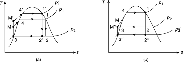
Figure 4.7 Effect of boiler and condenser pressure on Rankine cycle efficiency: (a) Effect of increase of boiler pressure, (b) Effect of decrease of condenser pressure
Leave a Reply