Although one is often more concerned with air noise emanating from grilles and diffusers in an occupied area, careful consideration should also be given to noise which may be radiated directly from the outer casings of various system elements conveying air to or from the grille. For example, although ducts and mixing boxes are often situated in a ceiling plenum directly over critical acoustical areas, the possibility that radiated noise from these elements could give rise to a serious acoustical problem is usually not adequately considered. The system designer should, therefore, be aware of this possibility and be able to estimate the noise radiated from outer casings of these elements.
The main sources of radiated noise are ducts, mixing boxes, and often fan plenum chamber panels. These will now be dealt with separately.
13.9.1 Duct‐Radiated Noise
The noise radiated directly from the walls of a duct as a result of the flow of air inside can result in excessively noisy adjacent areas. This is usually caused by the poor low‐frequency transmission loss characteristics of duct walls which results in a rumble sound in the surrounding areas. An exact analysis of the low‐frequency transmission loss properties of rectangular and circular ducts is beyond the scope of this hook. However, it is sufficient to say that the mass law is obeyed at frequencies above that at which the cross‐sectional duct dimensions equals the acoustic wavelength, up to an octave below the critical frequency, fc, of the duct walls (usually 10–15 kHz). At low frequencies, when the duct dimensions are much smaller than the acoustic wavelength, the transmission loss is controlled by the stiffness of the duct walls. It is found that at frequencies well below the first acoustic cross mode in the duct, the transmission loss increases with frequency at a rate of 3 dB per octave rather than 5–6 dB per octave, as predicted by the mass law. The following empirical relationship has been found to be useful in predicting the effective transmission loss of a rectangular duct at low and high frequencies:
(13.23a)
where LWD, LWR = sound power levels within the duct, and radiated from its walls, respectively; and M = weight of duct wall (lb/ft2); SW = total duct wall area, for length considered (ft2); S = cross‐sectional area (ft2); d = largest duct cross‐sectional dimension (ft); and f = frequency (Hz), or
(13.23b)
where M = weight of duct wall (kg/m2); SW = total duct wall area, for length considered (m2); S = cross‐sectional area (m2); and d = largest duct cross‐sectional dimension (m).
Once the radiated sound power level has been calculated, the sound pressure level in the space around the duct can be calculated from
where R = room constant for the absorption in the surrounding space, sabins. The approximations used in the derivation of the above equation break down under certain conditions at very low frequencies or when very large lengths of duct are considered. Clearly the radiated sound power can never exceed the power within the duct, and if Eq. (13.24) should ever predict such a situation, then a power loss of 3 dB may be assumed as a fair estimate (see Eq. (13.25))
(13.25)![]()
Circular ducts have a greater stiffness than equivalent area rectangular ducts and are therefore found to radiate much less (5–10 dB) low‐frequency noise. For this reason, circular ducts should always be used in preference to rectangular ducts in areas where low‐frequency (rumble) radiated noise is likely to be a problem. It is found that lagging the duct externally (e.g. with 5 kg/m2 (l lb/ft2) lead also tends to reduce the radiated noise level by increasing the effective weight of the duct walls and by adding damping to them.
Although the designer is usually more concerned with attempting to reduce duct‐radiated noise, it should be pointed out that such a mechanism can sometimes be used advantageously. For example, the noise in supply ducts situated directly after a fan plenum chamber is usually “rich” in low‐frequency noise. These components may not be sufficiently attenuated by the time that the outlet grille is reached; therefore, some additional low frequency attenuation is required. In normal circumstances, the designer would have several alternatives for providing this additional low‐frequency attenuation, but these would usually involve the use of commercial silencers. However, often this low‐frequency attenuation can be achieved very inexpensively by allowing the low‐frequency noise to be transmitted out through the duct walls of a long run of thin‐walled rectangular duct out into noncritical areas of the building such as a storeroom. Alternatively, the noise may be allowed to pass out into a ceiling plenum lined with sound‐absorbing material and situated over an acoustically noncritical area.
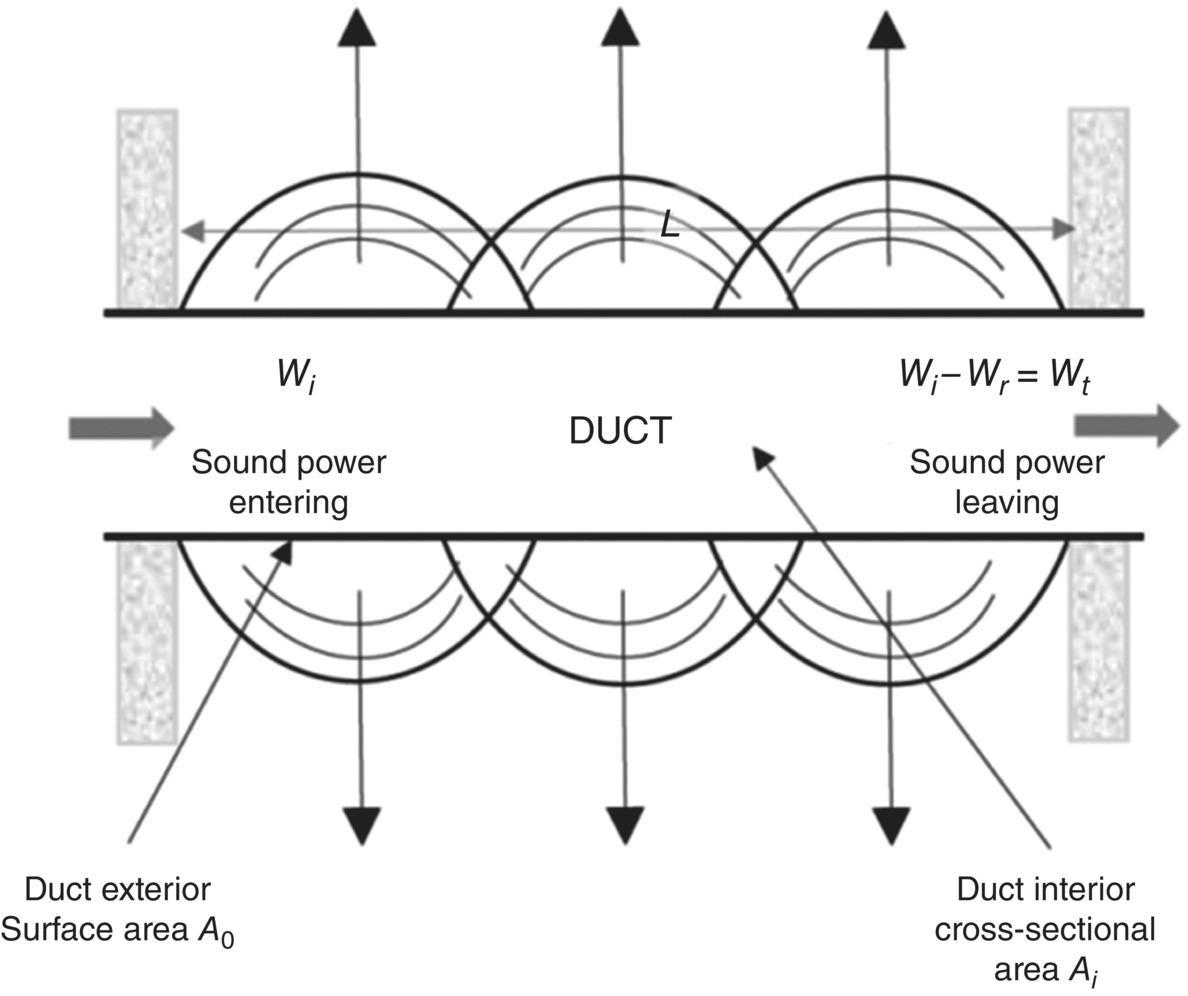
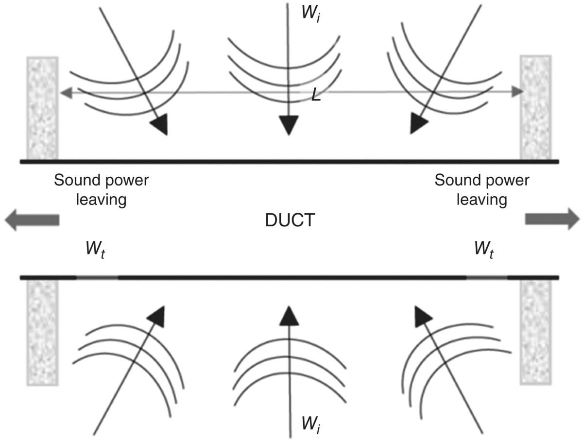
13.9.2 Sound Breakout and Breakin From Ducts
Breakout sound is caused by the fan or airflow noise inside a duct. This noise can be transmitted through the duct walls and then radiated into the surrounding space (Figure 13.70). Breakout noise should be adequately attenuated before the duct runs over or through an occupied space. Sound that is transmitted into a duct from the surrounding area is called breakin (Figure 13.71). The main factors affecting breakout and breakin sound transmission are the transmission loss of the duct, the total exposed surface area of the duct, and the presence of acoustical duct lining. The breakout sound power transmitted is given by [20]
(13.26)![]()
where LW(out) = sound power level of sound radiated from the outside surface of duct walls, dB; LW(in) = sound power level of sound inside duct, dB; S = surface area of outside sound‐radiating surface of duct, m2; A = cross‐section area of inside of duct, m2; TLout = normalized duct breakout transmission loss, dB.
Equation (13.26) is a simplified expression that assumes that the sound power level inside the duct does not decrease with distance over the length of the duct. For very long ducts (when S >> A), the radiated sound power level. Equation (13.26) predicts that LW(out) could become greater than the sound power level inside the duct, which would violate the conservation of energy principle. A more accurate expression for breakout sound is presented in the ASHRAE Handbook which allows for attenuation of the sound along the duct section. Values of TLout for rectangular ducts, round ducts and for flat oval ducts are given in the ASHRAE Handbook [20].
Equations for S and A for rectangular ducts are
(13.27)![]()
(13.28)![]()
where a = larger duct cross‐section dimension, m; b = smaller duct cross‐section dimension, m; L = length of duct sound‐radiating surface, m.
Equations for S and A for round ducts are
(13.29)![]()
(13.30)![]()
where d = duct diameter, m; L = length of duct sound‐radiating surface, m.
For flat oval ducts
(13.31)![]()
(13.32)![]()
where a = length of major axis, m; b = length of minor axis, m; L = length of duct sound‐radiating surface, m.
Equation (13.26) assumes no decrease in the internal sound power level with distance along the length of the duct. Thus, it is valid only for relatively short lengths of unlined duct. The ASHRAE Handbook deals with long ducts or ducts that have internal acoustical lining [20]. In most rooms where the listener is close to the duct, an estimate of the breakout sound pressure level can be obtained from
(13.33)![]()
where Lp = sound pressure level at a specified point in the space, dB; LW(out) = sound power level of sound radiated from the outside surface of duct walls, dB, given by Eq. (13.26); r = distance between duct and position for which Lp is calculated, m; L = length of the duct sound‐radiating surface, m.
Note that Eq. (13.33) gives the sound pressure radiated from a duct that is in a wide‐open ceiling plenum space. If the duct is in a restricted space between floor slab and ceiling, the level may be up to 6 dB higher.
EXAMPLE 13.14
A 610 mm × 610 mm × 7.5 m long rectangular supply duct is constructed of 0.75 mm sheet metal. Given the following sound power levels produced for a 0.75 m diameter backward‐curved centrifugal fan in the duct, what are the breakout sound pressure levels 2.5 m from the surface of the duct?
SOLUTION
Using Eqs. (13.26) and (13.33), the sound pressure level in the room is calculated and given in Table 13.20. It is observed that the low frequency levels below 500 Hz are quite high. The A‐weighted level which is only about 50 dB is probably acceptable for many spaces in a building and in particular store rooms.
Table 13.20 Sound pressure level predictions for breakout noise in Example 13.14.
| One‐Octave Band Center Frequency, Hz | |||||||||
|---|---|---|---|---|---|---|---|---|---|
| 63 | 125 | 250 | 500 | 1000 | 2000 | 4000 | 8000 | BPF | |
| Sound Power Level, dB | 85 | 85 | 84 | 79 | 75 | 68 | 64 | 62 | 3 |
| −TLout | −20 | −23 | −26 | −29 | −32 | −37 | −43 | −45 | |
| 10log S/A | +18 | +18 | +18 | +18 | +18 | +18 | +18 | +18 | |
| LW(out) | 83 | 80 | 80 | 68 | 65 | 49 | 39 | 35 | |
| −10log (πrL) | −18 | −18 | −18 | −18 | −18 | −18 | −18 | −18 | |
| Sound Pressure Level, dB | 65 | 62 | 62 | 50 | 47 + 2 BPF = 49 | 31 | 21 | 17 | |
13.9.3 Mixing Box Radiated Noise
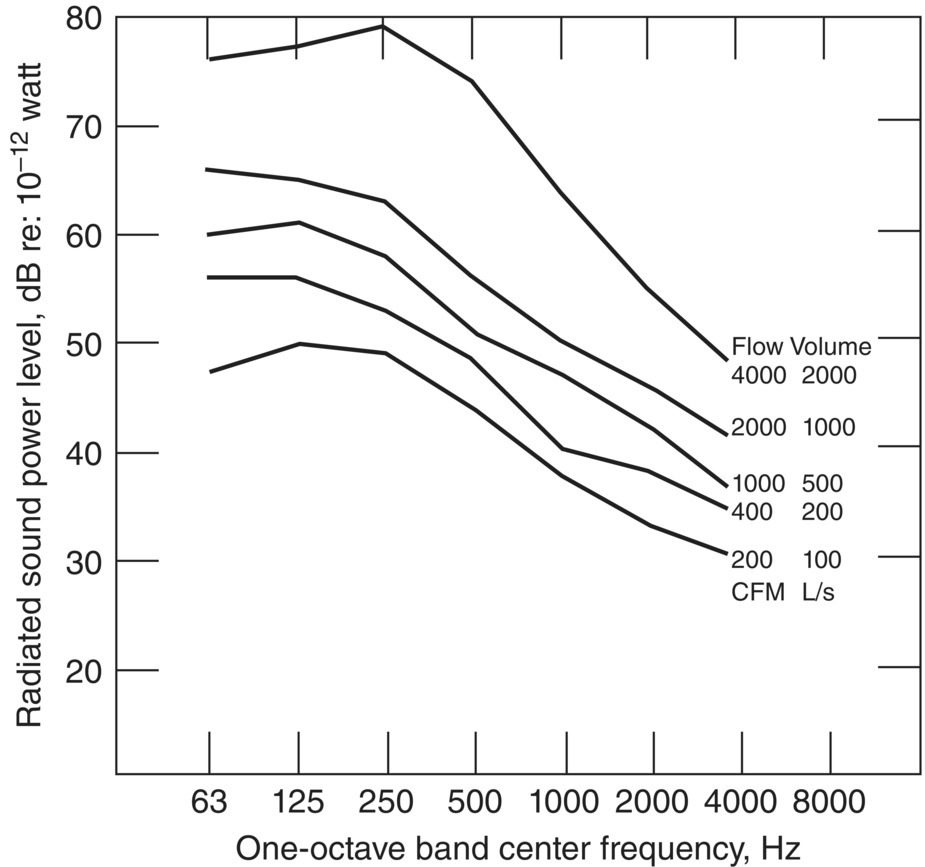
Noise radiating from the outer metal case of mixing boxes into a ceiling plenum space can also result in a significant acoustical problem. Indeed, high‐velocity mixing boxes should always be placed as far away as possible from critical acoustical areas and positioned over corridors or other high noise level regions of a building. The careful selection and positioning of mixing boxes are, therefore, of primary importance for good acoustical conditions, and manufacturers’ figures for measured radiated sound power levels should be consulted whenever possible. Some typical radiated sound power levels are shown in Figure 13.72 for dual‐inlet mixing boxes for various airflow volumes for a 375 Pa (1.5 in. water) static pressure drop. For other static pressure drops, a correction of 20 log (P/375) dB for SI units (or 20 log (P/1.5) dB where P is inches water) should be added to these sound power levels.
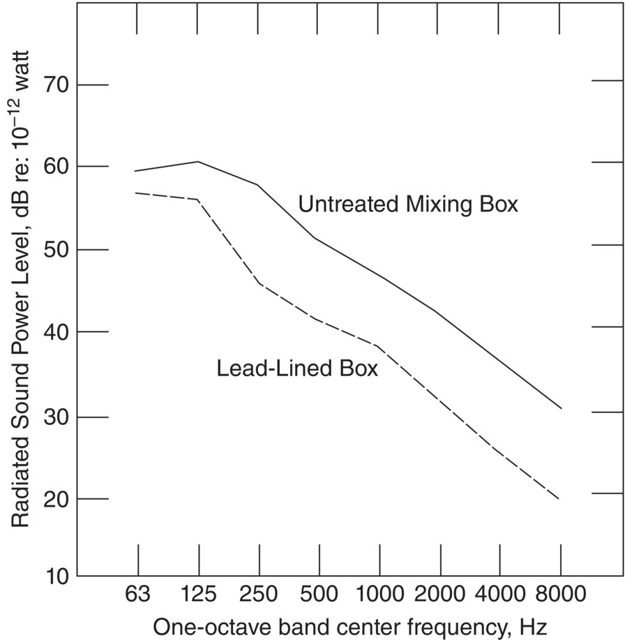
Since the radiated noise level is dependent upon the pressure drop across the box, it is advisable to choose a box with the lowest possible pressure differential and to arrange to take up the extra pressure elsewhere – for example, at an elbow, take‐off, or attenuator. Several manufacturers now provide mixing boxes with lead‐lined aluminum casings which can reduce the radiated sound power by 5–10 dB at low frequencies and 15–20 dB at high frequencies. The effect is shown in Figure 13.73.
A reduction in the radiated noise may also be obtained by:
- Bolting the unit hard against a structural slab. This allows the box to dissipate energy into the slab and also reduces the total radiating area. Such a procedure can reduce the radiated noise by as much as 3 dB throughout the frequency spectrum.
- Making the inlet connections to the box acoustically tight but flexible. If possible, the inlet connection should be covered with plaster or some other similar material to reduce the low‐frequency noise transmitted through the connector.
- Fitting the entire box within a metal airtight shroud. This can often reduce the radiated noise level by 10–15 dB. For example, an unshrouded box operating at 25.3 m3/min, 425 L/s (900 ft3/min) and 750 Pa (3 in. water) pressure drop may produce a noise spectrum corresponding to Noise Criterion NC45; however, when this box is enclosed in a separate shroud, this level may be reduced to Noise Criterion NC30.
13.9.4 Radiation From Fan Plenum Walls
It is often necessary to estimate the reverberant sound pressure level within a fan room in order to determine if sound transmission through the fan room walls or floor may create a problem in adjacent areas. This involves an estimation of the sound transmission loss of the fan plenum chamber. Fortunately, the material used in such constructions is usually 14–18‐gauge galvanized steel which has a relatively high critical frequency, in the range 8–25 kHz. This means that the “mass law” gives a fairly good estimate of its transmission loss characteristics in the frequency range of interest: – for example, 200–8000 Hz. However, one should be particularly careful to avoid mechanical resonances in the walls of the fan plenum. These may be excited by the rotation of the fan rotor and can result in excessive low‐frequency noise in the surrounding space, from which it may be readily transmitted to other adjacent areas. Such resonances can usually be avoided by providing adequate mechanical vibration isolation between the fan and its surrounding plenum. However, if such a resonance phenomenon should be observed, then the problem is best solved by either stiffening the resonant panel or changing its dimensions, or by slightly altering the fan rotational speed.
13.9.5 Overall Sound Pressure Level Prediction
Once the fan system is chosen for a building for HVAC purposes, it is useful to predict the sound pressure level in different rooms and other occupied and non‐occupied spaces in the building. Commercial software is available to make the necessary calculations and to examine different ways to attenuate the sound. Examples of such software include the Trane Acoustic Program – Tap ™ version 2.3, the Vibro‐Acoustics® V‐A Select Release 5.0, and Acousticcalc (www.acousticcalc.com). Ryherd and Wang compare results from the first two softwares with a spreadsheet they developed in Ref. [14]. The calculations presented in Example 13.15 are based on the approach of Fry in Ref. [8]. If such software is not available, simple preliminary calculations such as in Example 13.15 may be useful. In the following example, assume that the direct, reverberant and total sound pressure levels can be calculated using Eqs. 13.34–13.36.
(13.34)![]()
(13.35)![]()
(13.36)![]()
where Lp (total) = total sound pressure level, dB; Lp (dir) = direct sound pressure level, dB; Lp (rev) = reverberant sound pressure level, dB; LW (per grille) = sound power level from each grille, dB; LW (to room) = sound power level entering rood, dB; QF = directivity factors; r = distance from source to receiver, m; T = reverberation time, s; and V = volume, m3.
EXAMPLE 13.15
Design a HVAC system for an office block as shown in Figure 13.74. Use an axial fan with volume flow 2 m3/s and pressure of 40 N/m2 to supply air to staff offices, the reception room and the store room. The primary duct work is 8 m long with cross‐section 915 × 610 mm and the secondary ducts are 615 × 305 mm and 610 × 610 mm. The total sound pressure level Lp (total) will be calculated at the critical distance from a grille by logarithmically adding Lp (dir) to Lp (rev). A distance of 0.8 m (2 ft) is assumed to be this distance. Allow for the mitre bend shown in the mechanical room and for the take‐offs to the directors’ and other staff offices using Eq. (13.17). Assume the diffusers are flush‐mounted in the ceiling away from the walls. The air flow to each diffuser is 0.25 m3/s.
SOLUTION
Using the Fry method, the in‐duct sound power level of the fan is calculated from Eq. (13.3). The reverberation time T and grille directivity factor will depend on frequency. For simplicity, we will assume T = 0.5 second and Q = 1 independent of frequency. Then,

Assume that 50% of the sound power is radiated equally in each direction to the fan inlet and exhaust. Thus, the supply in duct sound power is 75 − 3 = 72 dB. The steps in the calculation are shown as lines 1 through 17 of Table 13.21.
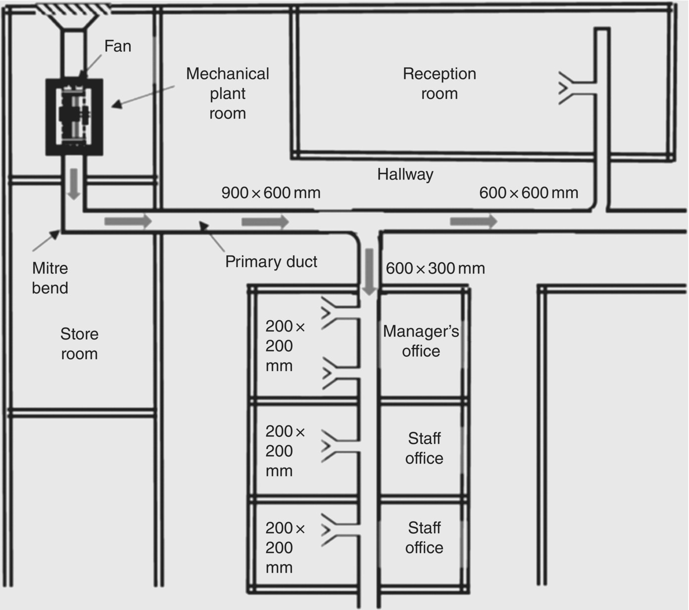
Table 13.21 Sound pressure level, dB, predicted in Example 13.15.
| Item | One-Octave Band Center Frequency (Hz) | ||||||||
|---|---|---|---|---|---|---|---|---|---|
| 63 | 125 | 250 | 500 | 1000 | 2000 | 4000 | 8000 | ||
| 1 | Fan sound power level | 72 | 72 | 72 | 72 | 72 | 72 | 72 | 72 |
| 2 | Fan correction | −5 | −5 | −6 | −7 | −8 | −10 | −13 | −15 |
| 3 | Corrected unit LW | 67 | 67 | 66 | 65 | 64 | 62 | 59 | 57 |
| 4 | 10 m 915 × 610 mm duct | −15 | −10 | −5 | −3 | −2 | −3 | −2 | −2 |
| 5 | 5 m 610 × 305 mm duct | −7 | −7 | −4 | −2 | −2 | −2 | −2 | −2 |
| 6 | Mitre bend | 0 | −5 | −8 | −4 | −3 | −3 | −3 | −3 |
| 7 | End reflection | −14 | −10 | −5 | −2 | 0 | 0 | 0 | 0 |
| 8 | LW Leaving system | 31 | 35 | 44 | 54 | 57 | 55 | 52 | 50 |
| 9 | % Lw to room = 20% | −8 | −8 | −8 | −8 | −8 | −8 | −8 | −8 |
| 10 | Volume and reverb time correction | −4 | −4 | −4 | −4 | −4 | −4 | −4 | −4 |
| 11 | Lp reverberant | 19 | 23 | 32 | 42 | 45 | 43 | 40 | 38 |
| 12 | LW to outlet 20% | −8 | −8 | −8 | −8 | −8 | −8 | −8 | −8 |
| 13 | Distance to listener | −4 | −4 | −4 | −4 | −4 | −4 | −4 | −4 |
| 14 | Lp direct | 19 | 23 | 32 | 42 | 45 | 43 | 40 | 38 |
| 15 | Lp total | 22 | 26 | 35 | 45 | 48 | 46 | 43 | 41 |
| 16 | NCB 30 Criterion | 55 | 46 | 40 | 35 | 32 | 29 | 25 | 22 |
| 17 | Additional attenuation needed | 0 | 0 | 0 | 10 | 16 | 17 | 18 | 19 |
Item: (1) Volume flow and pressure substituted in Eq. (13.3); (2) Fan correction from Table 13.3; (3) Corrected sound power level, LW; (4) Duct attenuation from Table 13.11 by combining each duct‐wall side attenuation calculated separately and combining; (5) Same procedure as (4) above; (6) Mitre bend without turning vanes or absorbing material. No attenuation assumed for secondary duct take‐offs (Table 13.18); (7) End reflection Figures 13.56 and 13.57 for duct exit flush in center of ceiling; (8) Sound power level LW leaving system wall; (9) LW leaving two grilles; (10) Reverb Time corrections; (11) Reverberant Lp; (12) LW to grilles; (13) Listener distance from grille 0.8 m (2.5 ft); (14) Lp direct; (15) Total Lp (reverb) + Lp (direct); (16) NCB 30 Criterion; (17) additional attenuation needed to meet NCB 30.
Example 13.15 shows that to meet the NCB 30 criterion requires substantial additional attenuation in the frequency range 500–8000 Hz. Various approaches could be used to achieve the attenuation required. (a) A centrifugal fan could be chosen instead of an axial‐flow one since low frequency is not of concern and centrifugal fans generate less high‐frequency noise. See Figure 13.15. However, the axial fan probably cannot be changed at this stage since it was chosen for HVAC reasons, not noise. (b) A lined mitre bend could be chosen (Figure 13.59 and Table 13.19) since the attenuation above 500 Hz is just sufficient. (c) Lined ducts (Figure 13.49) could be considered, since with sufficient lining thickness (25 or 50 mm) and 5 or 10 m length, adequate attenuation could be achieved. (d) A plenum chamber located either in the mechanical room, or soon after (Example 13.9 and the results of Table 13.10) would also be a good choice to achieve the necessary attenuation. (e) Mufflers could also be considered since they can provide more than adequate attenuation at this frequency
Leave a Reply