Pumps are used to transport liquids and suspensions of solid particles in hydraulic systems. The noise generated in such systems is produced not only by the pump but also by the driving motor (usually an electric motor with its cooling fan). The noise and vibration created is carried throughout the hydraulic system as fluid‐borne noise and mechanically by the pipe system itself as structure‐borne noise [74, 75] (personal communication with Cesare Angeloni, 9 February 2006).
There are three main types of pumps: (i) positive displacement, (ii) kinetic (i.e. dynamic), and (iii) special effect type. Some of the main pump designs are illustrated in Figure 11.19 [76] and are similar in many ways to compressors used to pump or transport gases as described in Section 11.3.3. Positive‐displacement pumps work by periodically adding energy to the fluid by one or more elements moving within a cylinder or pump case. In a similar way to positive displacement compressors, positive displacement pumps can be further subdivided into reciprocating and rotary types. The operation of a pump causes mechanical forces resulting in vibration, and even more important, pressure pulsations in the fluid, both of which cause noise. Rotary pumps can be divided into two main types: those possessing single rotors and those with multiple rotor elements. There are many different types of single‐ and multiple‐type pumps including vane, gear, lobe, and screw types as shown in Figure 11.19 [76].
The main sources of noise in reciprocating pumps include: (i) flow and pressure pulsations sometimes called “ripple,” turbulent and separated flows, and vortex formation in the fluid and (ii) unbalanced mechanical forces, inlet and discharge valve impacts, and piston slap. The main sources of noise in rotary pumps depend upon the pump design and include (i) fluid pressure pulsations, turbulence, and vortices and (ii) mechanical forces resulting from impacts between the teeth of gear pumps, the sliding of the vanes of vane pumps, and friction forces created in screw types of pumps. Gear pumps are noisy since they trap and compress the working fluid between the gear teeth and expel it in a direction perpendicular to the axis of revolution. They can operate at pressures of 150 bars or more. Screw pumps are generally much quieter and move the fluid in a direction parallel to the screw axis but are limited to lower pressures, usually less than about 40 bars.
Empirical expressions for the overall A‐weighted sound power level of different types of pumps are listed in Table 11.6 [76]. Here QBEP corresponds to the flow at the design or best efficient point of the pump. Equations in Table 11.6 are valid for a limited range of the power consumption within which the measurements were done, and by taking into account a certain degree of uncertainty.
Table 11.6 Prediction of the A‐weighted sound power level generated by different pumps [76].
| Type of pump | A‐weighted sound power level, (P in kW, Pref = 1 kW) in dB | Valid for power consumption P |
|---|---|---|
| Centrifugal pumps (single stage) | LWA = 71 + 13.5 log P ± 7.5 | 4 kW ≤ P ≤ 2,000 kW |
| Centrifugal pumps (multistage) | LWA = 83.5 + 8.5 log P ± 7.5 | 4 kW ≤ P ≤ 20,000 kW |
| Axial‐flow pumps | LWA = 78.5 + 10 log P ± 10 at QBEP | 10 kW ≤ P ≤ 1,300 kW |
| LWA = 21.5 + 10 log P + 57Q/QBEP ± 8 | 0.77 ≤ Q/QBEP ≤ 1.25 | |
| Multipiston pumps (inline) | LWA = 78 + 10 log P ± 6 | 1 kW ≤ P ≤ 1,000 kW |
| Diaphragm pumps | LWA = 78 + 9 log P ± 6 | 1 kW ≤ P ≤ 100 kW |
| Screw pumps | LWA = 78 + 11 log P ± 6 | 1 kW ≤ P ≤ 100 kW |
| Gear pumps | LWA = 78 + 11 log P ± 3 | 1 kW ≤ P ≤ 100 kW |
| Lobe pumps | LWA = 84 + 11 log P ± 5 | 1 kW ≤ P ≤ 10 kW |
EXAMPLE 11.10
A small screw pump of power consumption 2 kW is installed outdoors on the floor (assumed to be reflecting). If the pump ordinarily radiates equally well in all directions (omnidirectional), what is the A‐weighted sound pressure level to be expected at 2 m from the pump?
SOLUTION
First, we determine the A‐weighted sound power level from the respective equation in Table 11.6 as LWA = 78 + 11 × log(2) ± 6 = 81 ± 6 dB. Therefore, the expected sound power level would be between 75 dB and 87 dB. Since the pump is an omnidirectional source on a reflecting floor, use of Eq. (3.52) yields the A‐weighted sound pressure level at 2 m: Lp = LWA − 20 × log(2) − 8 dB = 81 ± 6 − 20 × log(2) − 8 = 81 ± 6 − 14 = 67 ± 6 dB. Thus, the expected A‐weighted sound pressure level at 2 m from the pump is predicted to be between 61 and 73 dB.
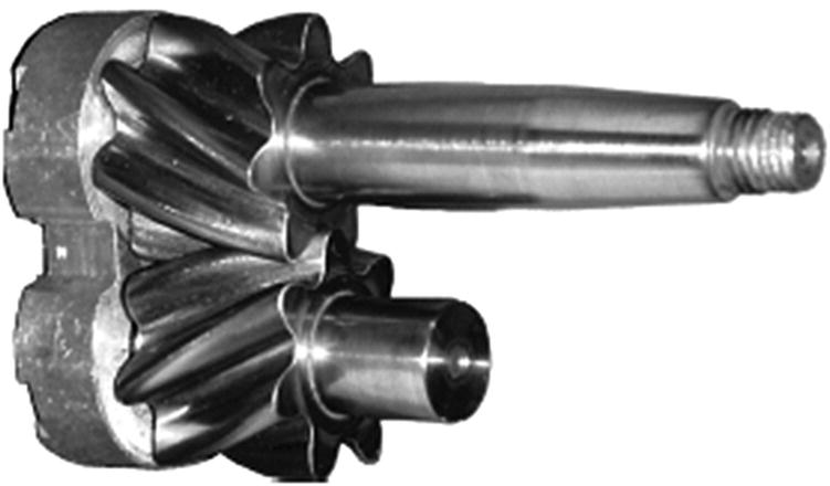
Various designs of pump have been produced to reduce ripple [75] (personal communication with Cesare Angeloni, 9 February 2006). One novel design has gear/screw elements that makes it a cross between a gear and screw pump (see Figure 11.20). The two contra‐rotating elements tend to balance internal forces and torques thus reducing vibration and noise. It is claimed that this type of pump, termed a Continuum® pump, virtually eliminates the trapping of fluid between gear teeth by using special helical gears, which results in much less pressure ripple and pump noise. The pump can operate at speeds up to 5000 rpm and pressures as high as 240 bars. Figure 11.21 shows the pressure pulsations (ripples) for two different designs of gear pump and the Continuum pump when they were all operated at 1500 rpm and a pressure of 100 bars. It is seen that these continuous‐contact pumps exhibit a much smaller magnitude of ripple. Figure 11.22 presents the A‐weighted sound pressure levels measured using the ISO 4412 method for two gear pumps and the continuous‐contact pump when they were tested under similar operating conditions. The overall A‐weighted sound pressure level of the continuous‐contact pump does appear to be of the order of 5–8 dB lower than the noise levels of the two other pumps and supports the idea that the pressure ripple is a major source of noise in most pump types.
The flow and pressure ripple effects can also be reduced by the use of dampers or accumulators and/or by very careful and precise manufacturing and grinding of the parts of the pump. Dampers can be similar to muffler expansion chambers in design or have special design features including flexible membrane parts to absorb the pressure pulsations. Efforts continue to be made to reduce pump ripple [77] and cavitation [78, 79], which can cause serious damage to pumps and hydraulic systems. Different methods are used to improve pump design [80–82] and also for diagnostics and health maintenance of pumps and hydraulic systems [83, 84]. Precision grinding of parts does add cost and this must be considered in choosing a pump system.
It should be noted that pump pressure pulsations produce vibrations of the pump case, pipe wall or any other structure to which the pump system is attached. These pulsations may also be transported through the pipe structure and the fluid, resulting in noise radiation to the surrounding air. Reduction of these pulsations can be achieved by installing flexible connectors, mufflers, dampers, expansion chambers, side‐branch tuned resonators or using flexible couplings, among others. Figure 11.23 shows some devices for reducing structure‐borne noise produced by pressure pulsation in piping. Reference [76] presents a detailed review of the noise of pumps and pumping systems.
Leave a Reply