The psychrometric processes by which the state of moist air can be altered are shown in Fig. 20.7. These processes are:
- Sensible heating-process OA
- Sensible cooling-process OB
- Humidifying-process OC
- Dehumidifying-process OD
- Heating and humidifying-process OE
- Cooling and dehumidifying-process OF
- Cooling and humidifying-process OG
- Heating and dehumidifying-process OH
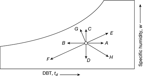
Figure 20.7 Basic psychrometric processes
1 Sensible Heating or Cooling Process
The heating/cooling of air without any change in its specific humidity is known as sensible heating/cooling. The process of sensible heating (line 1-2) or cooling (line 2-1) is shown by a horizontal line in Fig. 20.8. In this process, the specific humidity of air remains constant, i.e. w1 = w2. The heat has to be transferred which goes to change the temperature of air. The sensible heat transfer rate is given by,
Q̇s = ṁa (h2 − h1)
= ṁa [cpa (t2 − t1)+ wcpv (t2 − t1)]

= ṁa cp (t2 − t1)
where cp = cpa + wcpv = humid specific heat
ṁa = mass flow rate of dry air, kg d.a./s
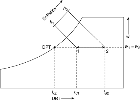
Figure 20.8 Sensible heating process
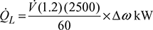
![]() = Volume of air V̇ in m3/min × density of air ρ in kg/m3
= Volume of air V̇ in m3/min × density of air ρ in kg/m3
For the purpose of calculations, standard air is taken at 20°C and 50% RH. The density of standard air is approximately 1.2 kg/m3 d.a. The value of humid specific heat is taken as 1.0216 kJ/(kg d.a.)(K)

The sensible heating of moist air can be done to any desired temperature. But the sensible cooling can be done only up to the dew point temperature tdp, as shown in Fig. 20.8.
2 Humidification or Dehumidification Process
Humidification is the addition of moisture to air without change in its DBT. Similarly dehumidification is the removal of moisture without change in DBT. When the state of air is altered along the constant DBT line, such as 1-2 in Fig. 20.9, moisture in the form of vapour has to be transferred to change the humidity ratio of air. This transfer of moisture is given by,

Because of this change in humidity ratio, there is also a change in the specific enthalpy of air, as shown in Fig. 20.9. This change in enthalpy due in the change in humidity ratio is considered to cause a latent heat transfer, given by
Q̇L = ṁa(h2 − h1) = ṁa[(cptd2+hfgw2) − (cptd1 + hfgw1)]
Since td1 = td2

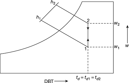
Figure 20.9 Humidification or dehumidification
where hfg = latent heat of vaporisation at td1

3 Heating and Humidification
This process involves both a change in temperature as well as in the humidity ratio as shown in Fig. 20.10. The change in temperature causes a sensible heat load, given by,
Qs = ṁa (hA − h1) = ṁacp (td2 − td1)
The change in humidity ratio causes a moisture transfer, given by
G = ma (w2 − wA) = ma (w2 − w1)
Latent heat load QL =ma (h2 − hA) = mahfg (w2 − w1)


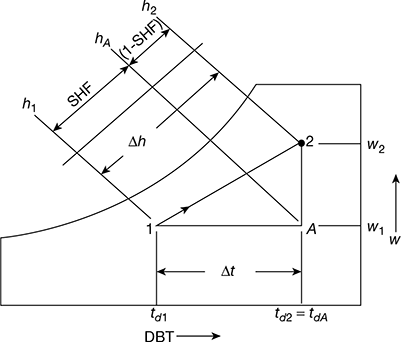
Figure 20.10 Heating and humidification
4 Sensible Heat Factor-SHF
The ratio of the sensible heat transfer to the total heat transfer is termed as the sensible heat factor.
Thus

The process line 1-2 is called the sensible heat factor line (or process or condition line). The point A divides the total enthalpy change ![]() in the ratio of SHF and (1 − SHF). Qs is proportional to SHF and QL to (1 − SHF).
in the ratio of SHF and (1 − SHF). Qs is proportional to SHF and QL to (1 − SHF).
5 Cooling and Dehumidification
In this process, the DBT as well as specific humidity of air decreases. The final relative humidity of the air is generally higher than that of the entering air. This is achieved by passing the air over a cooling coil or through a cold water spray. The effective surface temperature of the coil is known as apparatus dew point (ADP). The cooling and dehumidification process is shown in Fig. 20.11.
Qs = hA − h2
QL = h1 − hA
Q = Qs + QL = h1 − h2
Figure 20.11 Cooling and dehumidification


6 Air Washer
The schematic representation of an air washer is shown in Fig. 20.12. It involves the flow of air through a spray of water. During the course of flow, the air may be cooled or heated, humidified or dehumidified, or simply adiabatically saturated, depending on the mean surface temperature of water. The water is, accordingly, externally cooled or heated or simply circulated by a pump. Make-up water is added for any loss in the case of humidification of air. Eliminator plates are provided to minimise the loss of water droplets.
The thermodynamic changes of state of air along path 1-2 in an air washer, depending on the mean surface temperature of water droplets ts (equal to tu), is shown in Fig. 20.13. The following processes are possible:
- Process 1-2a: Heating and humidification (ts > td1). The water is externally heated.
- Process 1-2b: Humidification (ts = td1). The enthalpy of air increases. The water is externally heated.
- Process 1-2c: Cooling and humidification (tw1 < ts < td1). The mean surface temperature of water is greater than the wet bulb temperature of air, tw1. The enthalpy of air increases as a result of humidification. The water has to be externally heated.
- Process 1-2d: Adiabatic saturation (tw1 = ts). The water is simply recirculated without any external heating or cooling.
- Process 1-2e: Cooling and humidification (tdp < ts < tw1). The enthalpy of air decreases. The water is required to be externally cooled.
- Process 1-2f: Cooling (ts = tdp). Water is required to be cooled.
- Process 1-2g: Cooling and humidification (ts < tdp). The condition line drawn from the initial state 1 is tangential to the saturation line.
The mass balance of an air washer is shown in Fig. 20.14.
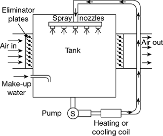
Figure 20.12 Air-Washer
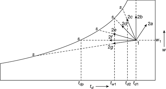
Figure 20.13 Range of psychrometric processes with an air washer
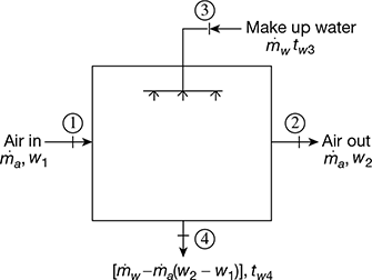
Figure 20.14 Mass balance of an air washer
Let ṁa = mass flow rate of dry air
ṁw = mass flow rate of water
Energy balance gives,
ṁa (h2 − h1) = ṁwcpwtw3 − [ṁw − ṁa (w2 − w1)]cpwtw4
or ṁa (h2 − h1) = ṁwcpw(tw3 − tw4)tw3 + ṁa(w2 − w1)cpwtw4
Neglecting the effect of temperature of water in the last term, we have


For adiabatic saturation case, dh = 0
dtw = 0 and tw3 = tw4


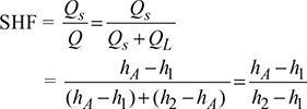
7 Cooling with Adiabatic Humidification
When the air is passed through an insulated chamber, as shown in Fig. 20.15(a), having water sprays maintained at a temperature (tf) higher than the DPT of entering air (tdp1), but lower than its DBT (td1) of entering air or equal to the WBT of entering air (tw1), then the air, is said to be cooled and humidified. Since the chamber is insulated and same water is circulated again and again, therefore, a condition of a adiabatic saturation is reached. Ultimately tf = tw1. This process is shown by line 1-3 in Fig. 20.15(b). This line follows the path along constant WBT line or constant enthalpy line.
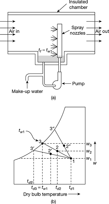
Figure 20.15 Cooling with adiabatic humidification
For perfect humidification, the final condition of air will be at point 3, where td3 = tw1. In actual practice the humidification is not perfect, therefore the final condition of air at outlet will be represented by point 2 on line 1-3.
Effectiveness or humidifying efficiency of spray chamber, for tf = tw1, is given by
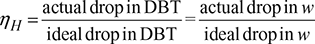

When tf < tw1, then the process follows the path 1-2′-3′. In that case

When tf > tw1, then the process follows the line 1-2′′-3′′. In that case

8 Cooling and Humidification by Water Injection
(Evaporative Cooling)
Let liquid water at temperature tf be injected and sprayed into air stream with the help at nozzles. The condition of air will change depending on the amount of water that evaporates. The enthalpy of evaporation will come from the enthalpy of air. The process is shown in Fig. 20.16.
Let ṁa = mass flow state of air
ṁv = mass flow rate of water evaporated
= mass flow rate of water supplied.
hf = enthalpy of liquid water
Then mass and enthalpy balances given


The term (w2 − w1) hf is extremely small as compared to h1 and h2.
Hence h1 = h2. Thus the water injection process is a constant enthalpy process, irrespective of the temperature of injected water.
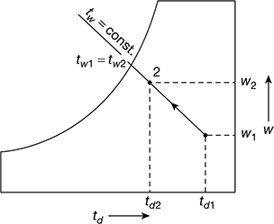
Figure 20.16 Cooling and humidification by water injection
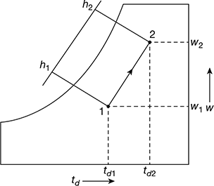
Figure 20.17 Heating and humidification by steam injection
9 Heating and Humidification by Steam Injection
Steam is normally injected into fresh outdoor air which is then supplied for the conditioning of textile mills where high humidity needs to be maintained. The process is shown in Fig. 20.17. If ms is the mass of steam supplied with enthalpy hs and ma the mass of air, then from the mass balance,

and for the enthalpy balance,

10 Heating and Adiabatic Chemical Dehumidification
This process is mainly used in industrial air-conditioning. It can also be used for some comfort air-conditioning requiring low relative humidity or low dew point temperature in the room. In this process, the air is passed over chemicals which have infinity for moisture. As the air comes in contact with these chemicals, the moisture gets condensed out of air and gives up its latent heat. Due to condensation, the specific humidity decreases and the heat of condensation supplies sensible heat for heating of air. As a result of this the DBT increases. The process is shown in Fig. 20.18 by line 1-2. The path followed during the process is along the constant WBT line or constant enthalpy line.
The chemicals used are hygroscopic solutions or brines of calcium chloride, lithium chloride, lithium premie and ethyl glycol. These are called absorbents which undergo a chemical or physical or both changes during taking moisture. The other type of chemicals are called adsorbents which are in the solid state to take up moisture but do not undergo changes chemically or physically. These include silica gel and activated alumina. The effectiveness or efficiency of the dehumidifier,
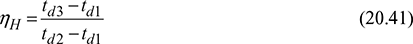
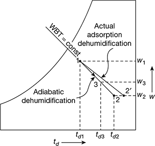
Figure 20.18 Heating and adiabatic chemical dehumidification
Leave a Reply