Modern‐day piezoelectric accelerometers and some of the earlier displacement transducers [23] work on the same principle: A seismic mass m is supported on a spring of stiffness k and the whole is enclosed in a case (see Figure 7.13). The damping constant R in most applications is small, and it is neglected for simplicity in the following analysis (although it could easily be included).
If the vibrating member (test piece) is undergoing a time‐dependent displacement, y2(t), and the mass experiences a time‐dependent displacement, y1(t), then considering the forces acting on the mass m,
(7.3)![]()
The situation is identical to that studied in Chapter 2, except that there is no external force applied to the mass, and instead the test piece receives a displacement input, y2(t). The easiest variable to measure is the relative displacement y2 − y1. We will assume the test piece experiences simple harmonic motion:
(7.4)![]()
and, consequently in steady‐state conditions, the mass experiences simple harmonic motion, y1, at the same angular frequency ω:
(7.5)![]()
Note that A and B are written as complex quantities because y1 and y2 will not generally be in phase (see Section 2.4.1). From Eqs. (7.3)–(7.5) we obtain (noting that j2 = −1)
(7.6)![]()
(7.7)![]()
Rearranging Eq. (7.7) gives
(7.8)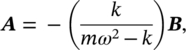
and substituting Eqs. (7.8) into (7.7) gives
(7.9)![]()
It is easy to see how this result can be used to design displacement, velocity, or acceleration transducers.
EXAMPLE 7.4
An accelerometer placed on an object vibrating sinusoidally measures an acceleration amplitude value of 4 m/s2. If the vibration frequency is known to be 50 Hz, calculate the corresponding velocity and displacement amplitudes.
SOLUTION
We know that ω = 2πf = 2π(50) = 314.16 rad/s.
Since the displacement for harmonic motion is y(t) = Ae jωt, where A is the displacement amplitude, the velocity is:

Therefore, we can see that the velocity amplitude and the acceleration amplitude are, respectively, v = ωA and a = ω2 A. Thus,


a) Seismic Mass Displacement and Velocity Transducers
Seismic mass displacement and velocity transducers were widely used until the 1950s. They required a large seismic mass and a soft spring and were operated well above the system’s natural frequency (between about 0.5 and 3 Hz) to obtain a flat frequency response curve. They were heavy and only suitable for use on heavy machinery [24]. The soft spring gave a low resonance frequency between about 0.5 and 3 Hz, but the upper frequency limit was normally about 100 Hz due to limitations in the mechanical linkages used to measure the motion of the mass relative to the system’s case. There are now several other displacement and velocity transducers available that do not suffer from this very limited frequency range. For example, the laser Doppler system can be used to measure dynamic displacement and velocity with a very high degree of precision.
b) Seismic Mass Acceleration Transducers
To measure acceleration conveniently with the seismic mass, the system shown in Figure 7.13 must be used as follows. The ratio of relative displacement amplitude |B − A| to test piece acceleration amplitude ω2| B| is from Eq. (7.9)
(7.10)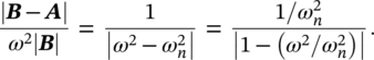
Except for the constant (![]() ) in the numerator, the right‐hand side of Eq. (7.10) is identical to that of Eq. (2.20) in Chapter 2 with δ = 0. If we had included damping in our model, the result would have again been identical to Eq. (2.20) in Chapter 2, except for the constant. Thus, we can make use of the results of Figure 2.9 in Chapter 2. This figure shows that we should like to operate the instrument in the stiffness‐controlled region, where ω/ωn << 1.
) in the numerator, the right‐hand side of Eq. (7.10) is identical to that of Eq. (2.20) in Chapter 2 with δ = 0. If we had included damping in our model, the result would have again been identical to Eq. (2.20) in Chapter 2, except for the constant. Thus, we can make use of the results of Figure 2.9 in Chapter 2. This figure shows that we should like to operate the instrument in the stiffness‐controlled region, where ω/ωn << 1.
Again this is obvious from Eq. (7.10), since, if ![]() << 1, the right‐hand side becomes a constant (equal to
<< 1, the right‐hand side becomes a constant (equal to ![]() ). To obtain a flat frequency response over a wide frequency range, ωn should be made large. But note that in this case the sensitivity decreases, since it is approximately proportional to
). To obtain a flat frequency response over a wide frequency range, ωn should be made large. But note that in this case the sensitivity decreases, since it is approximately proportional to ![]() . To obtain a large value of the frequency ωn, it is necessary to use a very stiff spring and a small mass, which is opposite to what is needed for seismic mass displacement and velocity transducers discussed above.
. To obtain a large value of the frequency ωn, it is necessary to use a very stiff spring and a small mass, which is opposite to what is needed for seismic mass displacement and velocity transducers discussed above.
EXAMPLE 7.5
The spring‐mass system of Figure 7.13 with m = 0.5 kg and k = 10 000 N/m, with negligible damping, is used as a vibration sensor. When mounted on a machine vibrating with an amplitude of 4 mm, the total displacement of the mass of the sensor is observed to be 12 mm. Find the frequency of the vibrating machine.
SOLUTION
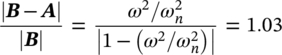
We find that |B| = 4 mm and |A| = 12 mm. Then, the relative displacement is |B − A| = |4–12| = 8 mm. From Eq. (7.10) we write that:

Now, ![]() = 141.42 rad/s. Therefore,
= 141.42 rad/s. Therefore,

EXAMPLE 7.6
The vibration transducer of Figure 7.13 is used to measure the vibration of an engine whose operating speed range is from 500 to 3000 rpm. The vibration consists of two harmonics. The amplitude distortion must be less than 3%. Find the natural frequency of the transducer if the damping is negligible.
SOLUTION
We select the accelerometer on the basis of the lowest frequency being measured (500 rpm). From Eq. (7.10) and considering 3% of error, we have that
 . Solving the equation gives
  . Therefore,
 ![]() . We find that ωn = 8.94 rad/s.
. We find that ωn = 8.94 rad/s.
Thus, the natural frequency of the accelerometer must be fn = 1.42 Hz.
It is possible to measure the relative displacement by attaching a strain gauge to the spring and calibrating the instrument by the change in resistance produced. This is the principle of the strain gauge accelerometer, which is normally used with a Wheatstone bridge. Such accelerometers will usually be found to have an upper frequency limit of about 1000 or 2000 Hz. Provided that the accelerometer is dc coupled, it is easy to calibrate the accelerometer by inverting it. If the strain gauge accelerometer is placed horizontally, there is no signal; placed vertically in one direction it gives a constant resistance change equivalent to +1 g and placed in the opposite vertical position the change is equivalent to −1 g. If the accelerometer is alternating current (ac) coupled, such calibration is not possible. However, the most commonly used type of accelerometer is now the piezoelectric accelerometer [25, 26].
Leave a Reply