Single-stage compression suffers from many disadvantages such as (i) handling of very high pressure range in one cylinder resulting in leakage past the piston, (ii) ineffective cooling of the gas, and (iii) necessitating robust construction of the cylinder to withstand the high delivery pressure.
The volumetric efficiency of a single-stage compressor with fixed clearance decreases with an increase in pressure ratio and thus reduces the capacity. Thus the necessity of of multi-stage compression with intercooling between stages are listed below:
- The air can be cooled perfectly at pressures intermediate between the suction and delivery pressures resulting in less power required as compared to a single-stage compressor for the same pressure limits and quantity of free air delivered.
- The mechanical balance of the machine is better due to phasing of the operations.
- The pressure range and hence the temperature range in each stage can be kept within desirable limits. This results in:
- Less loss of air due to leakage past the piston.
- More perfect lubrication due to lower temperatures.
- Better volumetric efficiency.
- The lighter construction of the machine that reduces the cost.
1 Two-stage Compressor
The schematic arrangement of two-stage compressor with intercooler and p − V diagram are shown in Fig. 12.11. The air is first taken into the low pressure (L.P.) cylinder at pressure p1. After compression to intermediate pressure p2, the air at condition 2 is passed through the intercooler and leaves it at point 3, where its temperature is reduced from T2 to T3. The air may be cooled to point 3′ such that T3′ = T1. Finally, the air is compressed in high pressure (H.P.) cylinder from condition 3 to 4 and is discharged to the receiver. Area 2–3–4–6–2 represents the work saved due to intercooling.
Figure 12.12 shows the p − V diagram for two-stage compression with perfect intercooling. Process 1–2 represents the polytropic compression in the L.P. cylinder with pV n1 = constant. Process 2–3 represents intercooling from T2 to T3 = T1. Process 3–4 represents the polytropic compression in the H.P. cylinder with pV n2 = constant. Curve 1–3–4′ represents the isothermal compression.
Total work done on the air,
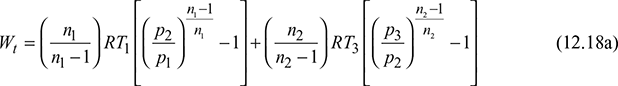
Let ![]() and
and ![]()
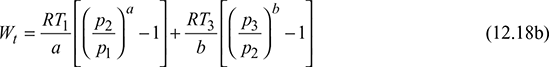
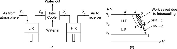
Figure 12.11 Two stage compression with intercooling: (a) Schematic arrangement, (b) p-V diagram
Figure 12.12 Two stage compression with perfect intercooling
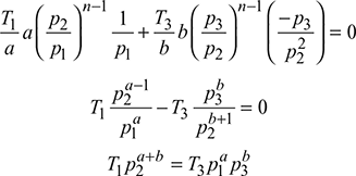
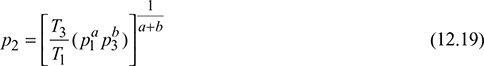
For p1 and p3 to be constant, intermediate pressure p2 must be determined for minimum work.
Thus,

For n1 = n2 = n, and a = b.
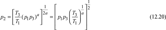
For perfect intercooling, T3 = T1. Thus,

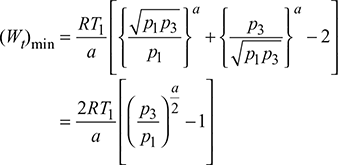
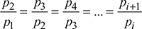
In general, with i number of stages, we have
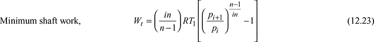
The minimum indicated powers (I.P.), with imperfect intercooling is:
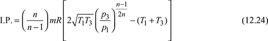
where m = mass of air delivered in kg per second
The number of stage is decided by the delivery pressure for a given inlet pressure (1 bar) as follows:
- For delivery pressure upto 5 bar: Single stage compressor
- For delivery pressure between 5 to 35 bar: Two stage compressor
- For delivery pressure between 35 to 85 bar: Three stage compressor
- For delivery pressure more than 85 bar: Four stage compressor
2 Heat Rejected to the Intercooler
Let m = mass of air in the cylinder
Then p1V1 = mRT1
or ![]()
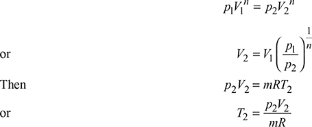
From the compression 1–2, we have
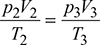
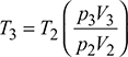
From the constant pressure line 2–3, we have

3 Cylinder Dimensions
For steady-state flow, the mass of air passing through each cylinder per stroke must be same.
Let Va = actual volume of air per stroke taken during suction
ρ = density of air
Then, Va1 ρ1 = Va2 ρ2 = Va3 ρ3 = … = const.
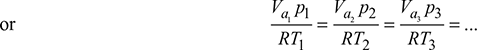
For perfect intercooling, T1 = T2 =T3 =…
∴ Va1 p1 = Va3 p2 = Va3 p3 =…
Vs1 ηv1 p1 = Vs2 ηv2 p2 = Vs3 ηv3 p3 =…
where ηv = volumetric efficiency of a cylinder
Vs = stroke volume of the cylinder


4 Intercooler and Aftercooler
Intercooler
An intercooler is a simple heat exchanger in which heat is removed from the air after it has been compressed and its temperature has risen as a result of compression. The intercooler commonly used is of the counter flow type as shown in Fig. 12.13 because it gives high effectiveness.
Effectiveness of intercooler,

A simple section showing the principles of construction of an intercooler is shown in Fig. 12.14. The coolant, which may be water or any other fluid, passes through the tubes secured between two end plates and the air circulates over the tubes through a system of baffles. Two passes are used for water flow and air is made to flow partly parallel and partly cross with the help of baffles. This type of intercooler gives better effectiveness than the ordinary counter-flow type. The purpose of the intercooler is to reduce the work done on the air.

Figure 12.13 Counter flow intercooler
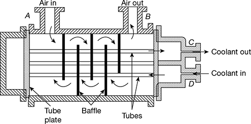
Figure 12.14 Principles of construction of inter-cooler
Leave a Reply