The efficiency of the Rankine cycle can be improved by the following methods:
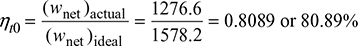
- Reheating
- Regeneration
- Combination of reheating and regeneration
1 Reheat Cycle
Figure 4.8(a) shows the schematic diagram for the reheat cycle. The corresponding h–s and T–s diagrams are shown in Fig. 4.8(b) and Fig. 4.8(c), respectively. The steam is extracted at a suitable point and is reheated with the help of flue gases in the boiler furnace. This increases the dryness fraction of steam passing through the LP turbine.
Heat supplied, qs = (h1 − hf6) + (h3 − h2)
Pump work, wp = hf 6 − hf5
Turbine work, wt = (h1 − h2) + (h3 − h4)
Net work output, wnet = wt − wp
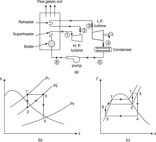
Figure 4.8 Reheat cycle: (a) Schematic diagram, (b) h-s diagram, (c) T-s diagram
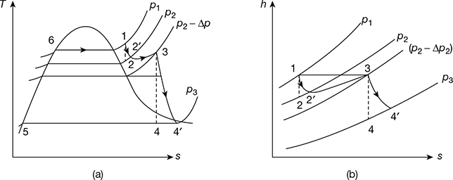
Figure 4.9 Reheat cycle with pressure drop between stages: (a) T-s diagram, (b) h-s diagram

If pump work is neglected,
2 Effect of Pressure Drop in the Reheater
The T-s and h–s diagrams for a reheat cycle with pressure drop is shown in Fig. 4.9(a) and (b), respectively. Steam enters the prime mover first stage at point 1. Line 1-2 is the isentropic process. However, in actual practice, it is an irreversible process due to internal frictional resistance offered to the flow of steam. Thus, the condition after the irreversible adiabatic expansion is shown by point 2′. The steam at condition 2′ is passed on the reheater. Since steam cannot pass through the reheater without a pressure drop, the exit from the reheater at point 3 account for the reheater pressure drop from p2 to p2 − Δp. The steam then expands irreversibly and adiabatically to point 4′.
For the first stage, turbine efficiency, ![]()
And for the second stage, ![]()

Example 4.4
A high pressure boiler delivers steam at 90 bar and 480°C. The steam is expanded in the first stage of turbine to 12 bar and withdrawn and passed on the reheater. The expansion now takes place in the second stage of the steam turbine, down to the condenser pressure of 0.07 bar. Calculate (a) the efficiency of the ideal cycle and (b) the work output and efficiency of the reheat cycle operating through the same states neglecting pump work.
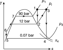
Figure 4.10 Reheat Rankine cycle
Solution
The cycle on T-s diagram is shown in Fig. 4.10.
At 90 bar, 480°C, from steam tables,
h1 = 3336.5 kJ/kg, s1 = 6.5942 kJ/kg.K
Now, s1 = s2
Since, sg at 12 bar is less than 6.5942, the state 2 is in the superheated region. then, we get
h2 = 2814.4 kJ/kg, t2 = 201°C
At 12 bar, 480°C, h3 = 3432.8 kJ/kg, s3 = 7.6198 kJ/kg.K
At 0.07 bar, sf4 = 0.5589 kJ/kg.K, sfg4 = 7.7179 kJ/kg.K
s3 = sf4 + x4sfg4
or 7.6198 = 0.5589 + x4 × 7.7179
or x4 = 0.915
h4 = hf4 + x4hfg4 = 163.40 + 0.915 × 2409.1 = 2367.7 kJ/kg
hfs = hf4 = 163.4 kJ/kg
h6 = h5 + wp
wp = vfs (p1 − p2) × 102
= 0.001007 (90 − 0.07) × 102 = 9 kJ/kg
h6 = 163.4 + 9 = 172.4 kJ/kg
- qa = (h1 − h6) + (h3 − h2) = (3336.5 − 172.4) + (3432.8 − 2814.4) = 3782.5 kJ/kgwnet = (h1 − h2) + (h3 − h4) − wp= (3336.5 − 2814.4) + (3432.8 − 2367.7) − 9 = 1578.2 kJ/kg
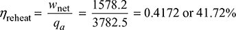
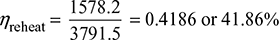
- Neglecting pump workqa = 3782.5 + 9 = 3781.5 kJ/kgwnet = 1578.2 + 9 = 1587.2 kJ/kg
Example 4.5
In Example 4.4, steam enters the reheater at 12 bar, 210°C, and leaves at 11.5 bar, 480°C. The combined steam rate is 3 kg/kWh, the generator efficiency is 94%, and the heat loss through the turbine casing is 1% of the throttle enthalpy. Determine the turbine thermal efficiency and condition of exhausted steam.
Solution
The processes in the T-s diagram is shown in Fig. 4.11.
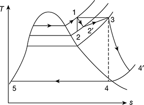
Figure 4.11 Reheat Rankine cycle with turbine efficiency
Refer to Fig. 4.11
![]() = 210°C,
= 210°C, ![]() = 12 bar, t3 = 480°C, p3 = 11.5 bar
= 12 bar, t3 = 480°C, p3 = 11.5 bar
Now h1 = 3336.5 kJ/kg, h2 = 2814.4 kJ/kg
![]() at 12 bar, 210°C from steam tables
at 12 bar, 210°C from steam tables
= 2839.8 kJ/kg
h3 at 11.5 bar, 480°C = 3433.4 kJ/kg
Now ![]()
For energy balance of turbine,
h1 + h3 = h′2 + ![]() + wnet + qloss
+ wnet + qloss
![]() = h1 −
= h1 − ![]() + h3 − wnet − 0.01 × h1
+ h3 − wnet − 0.01 × h1
= 3336.5 − 2839.8 + 3433.4 − 1276.6 − 0.01 × 3336.5 = 2620.1 kJ/kg
At p4 = 0.07 bar, ![]() = 2620.1 kJ/kg,
= 2620.1 kJ/kg, ![]() = 64°C
= 64°C
Since saturation temperature at 0.07 bar is 39.02°C, the exhaust steam is superheated and the degree of superheat is 24.98°C.
Efficiency of turbine upto extraction point,
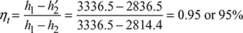
Overall efficiency of turbine,
Example 4.6
Steam at 100 bar and 500°C enters a prime mover that has one stage of reheat. The steam is exhausted from the prime mover at 0.07 bar and 85% dry. The net work developed by the prime mover is 1600 kJ/kg of steam. Calculate the thermal efficiency of the prime mover.
Solution
The cycle on T-s diagram is shown in Fig. 4.12.
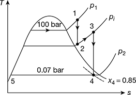
Figure 4.12 Reheat Rankine cycle
Refer to Fig. 4.12.
From steam tables for p1 = 100 bar, 500°C,
h1 = 3373.6 kJ/kg
At 0.07 bar, hf5 = 163.38 kJ/kg
h4 = hf4 + x4 hfg4
= 163.38 + 0.85 × 2409.2 = 2211.2 kJ/kg
wnet = 1600 kJ/kg
wnet = (h1 − h2) + (h3 − h4)
or h3 − h2 = wnet + h4 − h1 = 1600 + 2211.2 − 3373.6 = 435.6 kJ/hg
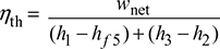
Thermal efficiency ηth = ![]()
Leave a Reply