The arrangement to measure the consumption of air by air-box method is shown in Fig. 11.12. It consists of an air-tight box fitted with a sharp-edged orifice of known coefficient of discharge. Due to the suction of engine, there is a pressure depression in the box which causes the flow through orifice for obtaining a steady flow. The pressure difference causing the flow through the orifice is measured with the help of a water manometer.
Let
A0 = area of orifice, m2
hw = head of water causing flow, cm
Cd = coefficient of discharge for orifice
d0 = diameter of orifice, cm
ρa = density of air, kg /m3
Head of air, ![]()
Velocity of air through the orifice,
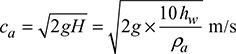
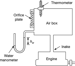
Figure 11.12 Measurement of air by air box method
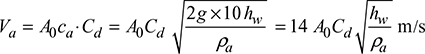
Volume of air passing through the orifice,
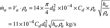
Mass flow rate of air passing through the orifice,

Density of air, ![]()
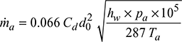
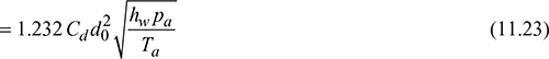
where hw is in cm, pa in bar and Ta in K
Mass of air supplied per kg of fuel used,

where N = % of N2 by volume in exhaust gases
C = % of carbon in fuel
C1, C2 = % of CO2 and CO by volume in exhaust gases.
Leave a Reply