The mean effective pressure is a quantity related to the operation of an internal combustion engine. It is a valuable measure of an engine’s capacity to do work that is independent of engine displacement.
1 Without Clearance
The theoretical p-v diagram for a single acting steam engine without clearance is shown in Fig. 5.9(a). It can be obtained by drawing a rectangle of area equal to the area of theoretical indicator diagram and base equal to the stroke volume, as shown in Fig 5.9(b).
Area under p-v diagram gives the work done per cycle by an engine, Work done per cycle w = (area l−2−2′−0−l) + (area 2−3 −3′−2′−2) − area (5−4−4′−0−5)

where p1 = steam admission pressure
p2 = release or cut-off pressure

Figure 5.9 p-v diagram without clearance
pb = back pressure
r = ![]() = expansion ratio
= expansion ratio
vs = v3 = swept volume
v2 = cut-off volume
v4 = v3, therefore
Now ![]()
Work done per cycle as represented by Fig. 5.9(b) is given by
w = pm. vs
or ![]()
From the above two equations, we get

2 With Clearance
The p-v diagram for a single acting steam engine with clearance is shown in Fig. 5.10(a). Work done per cycle is given by,
w = area 1-2-3-4-5 –1
=(area 1-2-2′-5′-1) + (area 2-3-3′-2′-2) − (area 5-4-3′-5′-5)


Clearance ratio, v3 = vc + vs = c vs + vs = (1 + c) vs
Expansion ratio, ![]()
Cut-off ratio, ![]()

Substituting the values of vc, v2 and v3, we get


Figure 5.10 p-v diagram with clearance


3 With Clearance and Compression
Figure 5.11 shows a hypothetical indicator diagram for a steam engine with clearance and compression. Clearance means the volume of gas left in the cylinder at the discharge end of the stroke. It includes the space between the piston and cylinder head, the volume of the valves, valve pockets etc. The various processes are:
Process 1-2: Steam admission at p1
Process 2-3: Hyperbolic expansion
Process 3-4: Steam released
Process 4-5: Exhaust of steam into condenser.
Process 5-6: Compression of remaining steam in cylinder
Process 6-1: entry of fresh from boiler into the cylinder rising the cylinder pressure suddenly to boiler pressure p1.
Work done per cycle w, = area l-2-3-4-5-6-1
= (area 1-2-2′-6′-1) + (area 2-3-3′-2′-2) − (area 5′-5-4-3′-5′) − (area 6′-6-5-5′-6′)


Figure 5.11 p-v diagram with clearance and compression

Let expansion ratio, ![]()
Swept volume, Vs = V3 − Vc
Clearance ratio, ![]()
V3 = Vc + Vs = cVs + Vs = (1+ c)Vs
Cut-off ratio ![]()

Compression ratio, ![]()
Vs = (α + c)Vs


4 With Clearance and Polytropic Expansion and Compression
A polytropic process can be expressed pvn = constant
The indicator diagram is shown in Fig. 5.12.
Work done per cycle.
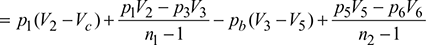
w = area l-2-3-4-5-6-1
= (area 1-2-2′-6′-1) + (area 2-3-3′-2′-2) − (area 5-4-3′-5′-5) − (area 6-5-5′-6′-6)
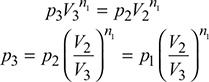
and ![]()

Let expansion ratio, ![]()
Swept volume, Vs = V3 − Vc
Clearance ratio, ![]()
V3 = Vc + Vs = cVs + Vs = (1+ c)Vs
Cut-off ratio ![]()

Compression ratio, ![]()

Figure 5.12 p-v diagram with clearance and polytopic expansion and compression


Leave a Reply