In all modern power plants, boilers raising steam at pressures greater than 100 bar are universally used. These are called high pressure boilers. They offer the following advantages:
- The efficiency and the capacity of the plant can be increased as reduced quantity of steam is required for the same power generation if high pressure steam is used.
- The forced circulation of water through the boiler tubes provides freedom in the arrangement of furnace and water walls in addition to the reduction in the heat exchange area.
- The tendency of scale formation is reduced due to high velocity of water.
- The danger of overheating is reduced as all the parts are uniformly heated.
- The differential expansion is reduced due to uniform temperature and this reduces the possibility of gas and air leakages.
1 Boiler Circulation
There are four types of boiler circulation as follows.
- Natural circulation: Water circulates naturally in a boiler when its density in one part of the circuit is less than that in another part at the same level. The boiler drums, tubes, and water wall make up the multi-passage circuit. During steam formation in a simple drum, the water near the sides of the drum gets heated and forms steam bubbles, lowering its density. The water in the drum centre being heavier displaces the lighter water-bubble mix and, in turn, gets heated up. This sets up a constant circulation that releases steam into the upper drum region.Similarly, in a water tube circuit, the water from the drum flows through the downcomer tube to the bottom of the heated riser. Heat forms steam bubbles in water passing through the riser, lowering the density of the mixture. The heavier downcomer water displaces the riser mixer to establish continuous flow. The force of gravity to produce flow in a natural circulation comes from the difference between the densities of the fluids in the downcomer and riser portions of the circuit. The natural circulation is depicted in Fig. 3.7(a).
- Forced circulation: Forced circulation in various circuits of boiler units is produced by mechanical pumps as depicted in Fig. 3.7(b).
- Once-through forced circulation: This type of circulation, as depicted in Fig. 3.7(c), receives water from the feed supply, pumping it to the inlet of heat-absorbing circuit. Fluid heating and steam generation take place along the length of the circuit until evaporation is completed. Further process through the heated circuits results in superheating the vapour.
- Once-through with recirculation (forced): The ‘recirculating’ forced-circulating type unit has water supplied to the heat absorbing circuits through a separate circulating pump. The water pumped is considerably in excess of steam produced and requires a steam-and-water drum for steam generation. This type of system is depicted in Fig. 3.7(d).
2 Advantages of Forced Circulation Boilers
The advantages of forced circulation boilers are as follows:
- Smaller bore and therefore, lighter tubes
- Absence from scaling troubles due to high circulation velocity
- Lighter for a given output
- Steam can be raised quickly and load fluctuations met rapidly
- Uniform heating of all parts eliminates the danger of overheating
- Greater flexibility in layout of boiler parts
- Boiler can be operated at desired conditions
- Boiler can be started rapidly
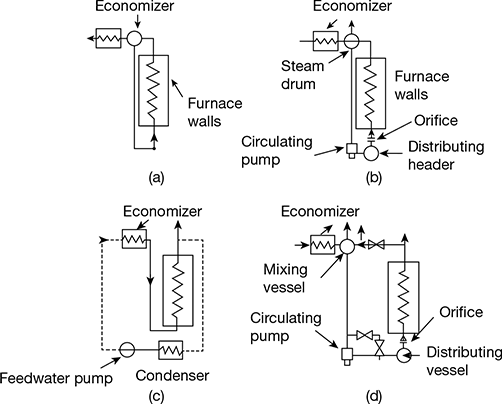
Figure 3.7 Types of boiler circulation: (a) natural circulation, (b) forced circulation, (c) once-through, (d) once-through with recirculation (force)
3 LaMont Boiler
This is a forced circulation boiler whose arrangement of water circulation and different components are shown in Fig. 3.8. Small diameter tubes are used in the evaporating section which gives flexibility in placing the heat transfer surfaces. The drum may be placed well away from the furnace. These boilers have been built to generate 45−50 tonnes of superheated steam per hour at a pressure of 150 bar, 500°C.
The feed water from the hot well is supplied to the boiler through the economiser. A pump circulates the water through the evaporator tubes and a part of the vapour is separated in the separator drum. The centrifugal pump delivers the water to the headers at a pressure above the drum pressure which distributes the water through the nozzle into the evaporator. The steam separated in the boiler is further passed through the superheater and then supplied to the prime mover.
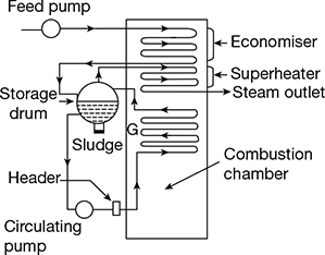
Figure 3.8 LaMont boiler
4 Benson Boiler
The major drawback in the LaMont boiler is the formation and sticking of bubbles in the inner surface of the heating tubes. These attached bubbles reduce the heat flow and steam generation as it offers higher thermal resistance as compared to water film. If the boiler pressure is raised to critical pressure (221.2 bar), the steam and water would have same density, and therefore, the danger of bubble formation can be completely eliminated.
The arrangement of the boiler components is shown in Fig. 3.9. The feed water is passed through the economiser and the radiant evaporator where a major part of water is converted into steam. The remaining water is evaporated by hot gases in the convective evaporator. The supercritical pressure steam is then passed through the superheater after which it is supplied to the prime mover.
The maximum pressure and temperature of steam obtained from this boiler are 500 bar and 650°C, respectively, and generating capacity of 150 tonnes/h. The major difficulty in the operation of this boiler is the deposition of salt and sediments on the inner surface of water tubes.
5 Loeffler Boiler
The major difficulty of Benson boiler is avoided in the Loeffler boiler by preventing the flow of water into the boiler tubes. Most of the steam is generated outside from the feed water by using a part of the superheated steam coming out from the boiler. The arrangement of different components and steam circulations is shown in Fig. 3.10.
The pressure feed pump draws the water through the economiser and delivers to the evaporator drum. About 65% of the steam coming out of superheater is passed through the evaporator drum to evaporate the feed water coming from the economiser. This steam is drawn by the steam circulating pump and passed through the radiant superheater and then convective superheater.
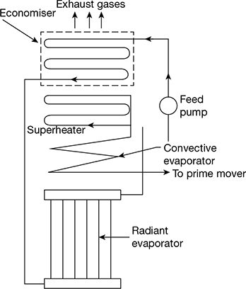
Figure 3.9 Benson boiler
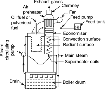
Figure 3.10 Loeffler boiler
Loeffler boilers are available with generating capacity of 94.5 tonnes/h and operating at 140 bar. This boiler can handle high drum salt concentration without trouble.
6 Schmidt-Hartmann Boiler
The arrangement of this boiler is shown in Fig. 3.11. In the primary circuit, a feed pump supplies water to drum through the economiser, which, in turn, discharges saturated steam to a convective superheater and then to load. A closed secondary circuit heated by furnace resembles a sectional header boiler. This section supplies the heated vapour in a coil to evaporate the main feed water. It has a tube evaporating section. These boilers are built for pressure ranging from 35−125 bar.
7 Velox Boiler
The arrangement of a Velox boiler is shown in Fig. 3.12. The pressurised combustion chamber (furnace) of this boiler uses low excess air and has high heat transfer rates. The air for the furnace is supplied by the air compressor. After heating water and steam, the combustion gases pass through a gas turbine to atmosphere. This gas turbine drives the axial flow compressor that raises incoming combustion air from atmosphere to the furnace pressure. The other important components are feed pump, economiser, steam separating section, water circulating pump, and convective superheater. This boiler is built for pressure ranging from 70−80 bar and 500°C.
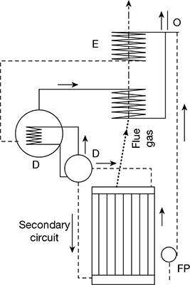
Figure 3.11 Schmidt-Hartmann boiler
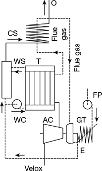
Figure 3.12 Velox boiler
8 Once-through Boiler
The arrangement of this boiler is shown in Fig. 3.13. It has inclined coils arranged in a spiral. Forty coils are paralleled around the furnace. Steam generated in the headers flows into headers and then to the convective superheater. Other essential components are the feed pump and economiser.
Leave a Reply