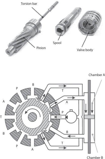
In the Figure below, a sketch of a HPAS system is depicted that shows pump, valve assembly, rack and the hydraulic cylinder. The most important part is the valve assembly having torsion bar in the core of the valve. The function of this bar is to activate the valve and at the same time transfer the applied manual force. The top part of the torsion bar is attached to the spool and the lower part is attached to the pinion.
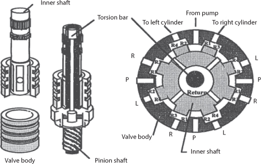
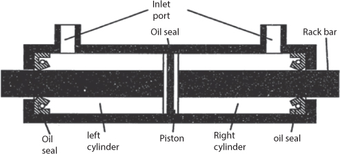
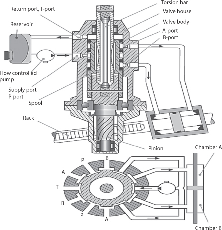
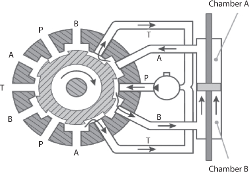
Figure of valve is shown below.
Where,
qs = pump flow
qL = load flow
Tsw = steering wheel torque
Cq = flow coefficient
Ps = pump pressure
pL = load pressure
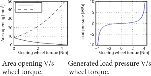
A = metering area
p = density of fluid
xr = lθw
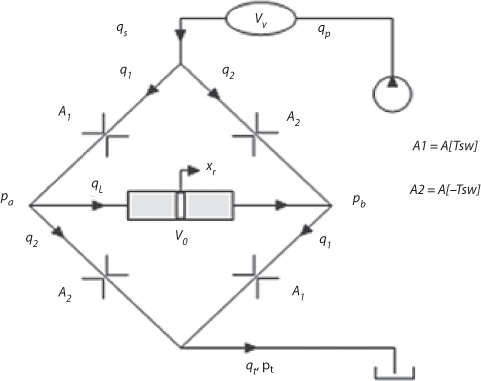
Where A1 and A2 are functions of the torsion bar angle.
Wheatstone Bridgerpresentation, where the multiple orifices are lumped together.
The quotient of load flow and system flow is defined. This can be simplified to a normalized flow, q. In a normalized flow q = 1, defines the limit of the rack speed, with maintained ability to generate assisting pressure.
Solved Example:
Assumption
Weight of vehicle = 1600 Kg
Front axle weight = 950 kg
Total force needed to steer wheel = 600 N
Steering arm length (l)=0.1
Return pressure (N/m2) =0
Pump flow rate (m3/s) =0.0002
Area of piston (m2) =0.001
Cylinder length (m) =0.15
Orifice flow coefficient = 0.6
Fluid density (Kg/m3) = 825
Fluid volume (m3) = 8.2 * 10–6
Fluid bulk modulus (N/m2) = 5.5 * 108
The steering wheel torque varies from Tsw = (0–15) Nm
The normalized flow  varies from (0–1)
Maximum pump pressure ![]() = (110–130 bar)
= (110–130 bar)
To find the assisting force when the steering wheel torque is at maximum and when q=1
When steering wheel angle increases the steering wheel torque increases from 0 and also the load pressure also increases as the driver steers one of the metering area increases while the other decreases.
Leave a Reply