Similar to the case of 16.12.6, it can be shown that

Example 16.1
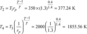
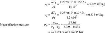
Calculate the indicated mean effective pressure and efficiency of a Joule cycle if the temperature at the end of combustion is 2000 K and the temperature and pressure before compression are 350 K and 1 bar, respectively. The pressure ratio is 1.3 and assume cp = 1.005 kJ/kgK.
Solution
Refer to Fig. 16.18.
p1 = 1 bar, T1 = 350 K, T3 = 2000 K
rp = 1.3, cp =1.005 kJ/kgK
wc = cp (T2 − T1) = 1.005 (377.24 − 350) = 27.376 kJ/kg
wt = cp (T3 − T4) = 1.005 (2000 − 1855.56) = 145.162 kJ/kg
Net work done, wnet = wt − wc = 145.162 − 27.376 = 117.786 kJ/kg
qs = cp (T3 − T2) = 1.005 (2000 − 377.24) = 1630.874 kJ/kg
Thermal efficiency ![]()
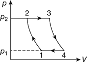
Figure 16.18 p-v diagram
Example 16.2
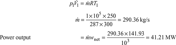
A gas turbine operates on a pressure ratio of 6. The inlet air temperature to the compressor is 300 K and the temperature of air entering to the turbine is 580°C. If the volume rate of air entering the compressor is 250 m3/s, calculate the net power output of the cycle. Also, calculate the efficiency.
Solution
The T-s diagram shown in Fig. 16.19
rp = 6, T1 = 300 K, T3 = 273 + 580 = 853 K
V̇1 = 250 m3 /s
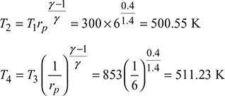
Compressor work wc = cp (T2 − T1) = 1.005 (500.55 − 300) = 201.55 kJ/kg
Turbine work wt = cp (T3 − T4) = 1.005 (853 − 511.23) = 343.48 kJ/kg
Net work output wnet = wt − wc = 343.48 − 201.55 = 141.93 kJ/kg
Heat input qs = cp (T3 − T2) = 1.005 (853 − 500.55) = 354.21 kJ/kg
Thermal efficiency ![]()
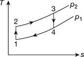
Figure 16.19 T-s diagram
Example 16.3
A gas turbine has a perfect heat exchanger. Air enters the compressor at a temperature and pressure of 300 K and 1 bar and discharges at 475 K and 5 bar. After passing through the heat exchanger, the air temperature increases to 655 K. The temperatures of air entering and leaving the turbine are 870°C and 450°C, respectively. Assuming no pressure drop through the heat exchanger, compute (a) the output per kg of air, (b) the efficiency of cycle, and (c) work required to drive the compressor.
Solution
The p – V and T-s diagrams are shown in Fig. 16.20.
T1 = 300 K, p1 = 1 bar,
T2 = 475 K, p2 = 5 bar,
T5 = 655 K, T3 = 870 + 273 = 1143 K,
T4 = 450 + 273 = 723 K
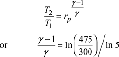
or γ = 1.4, cp = 1.005 kJ/kg
Compressor work wc = cp (T2 – T1) = 1.005 (475 – 300) = 175.9 kJ/kg
Turbine work wt = cp (T3 – T4) = 1.005 (1143 – 723) = 422.1 kJ/kg
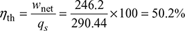
Heat input qs = cp (T3 – T5) = 1.005 (1143 – 655) = 490.44 kJ/kg
- Net work output, wnet = wt − wc = 422.1 − 175.9 = 246.2 kJ/kg
- Thermal efficiency,
- Compressor work, wc = 175.9 kJ/kg
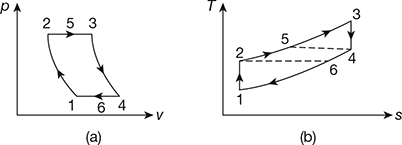 Figure 16.20 Diagrams for a gas turbine: (a) p-V diagram, (b) T-s diagram
Example 16.4
A closed cycle regenerative gas turbine operating with air has the following data: p1 = 1.4 bar,T1 = 310 K, rp = 5, Tmax = 1050 K, effectiveness of generator = 100%, net output = 3 MW. Calculate (a) the mass flow rate of air per minute and (b) the thermal efficiency.
Solution
The cycle in T-s diagram is shown in Fig. 16.21.
Refer to Fig. 16.21
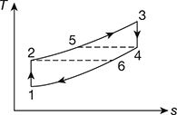
Figure 16.21 T-s diagram for closed cycle regenerative gas turbine
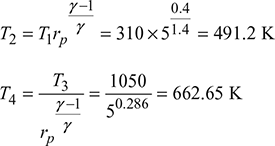
For 100% regenerative effectiveness,
T4 = T5 = 662.65 K
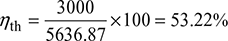
- wnet = ṁcp (T3 − T4 ) − ṁcp (T2 − T1) 3000 = ṁ ×1.005 [(1050 − 662.65) − (491.2 − 310)] ṁ = 14.48 kg/s or 868.8 kg/min
- Heat input Q = ṁcp (T3 −T5) = 14.48 × 1.005 (1050 − 662.65) = 5636.87 kJ/s Thermal efficiency
Example 16.5
The following data refers to a turbine with regenerator:
T1 = 290 K, T2 = 460 K, T3 = 900°C, T4 = 467°C
Calculate (a) the pressure ratio, (b) the specific work output, (c) the efficiency of cycle, and (d) the compressor work. Assume ηmech = 100%.
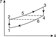
Figure 16.22 T-s diagram for a gas turbine with regenerator
Solution
The T-s diagram of the cycle is shown in Fig. 16.22.

 or rp = 5
- Work output, wnet =cp [(T3 − T4) − (T2 – T1)]= 1.005[(1173 − 740) − (460 − 290)]= 264.3 kJ/kg
- Heat input, qs = cth (T3 − T5) = cp (T3 − T4)= 1.005 (1173 − 740) = 435.165 kJ/kgThermal efficiency
- Compressor work, wc = cp (T2 − T1) = 1.005 (460 − 290) = 170.85 kJ/kg
Example 16.6
The ratio of net work to turbine work of an ideal gas turbine plant is 0.563. The temperature of air at the inlet to the compressor is 300 K. Calculate the temperature drop across the turbine if thermal efficiency of the unit is 35%. Assume a mass flow rate of 10 kg/s, cp = 1 kJ/kgK and γ = 1.4.
Solution
Thermal efficiency 
or 
or rp = 4.51
Compressor work wc = cp (T2 − T1) = 1 × (461.54 − 300) = 161.54 kJ/kg
or wt = 369.66 kJ/kg = cp · ∆T
ΔT = 369.66°C
Example 16.7
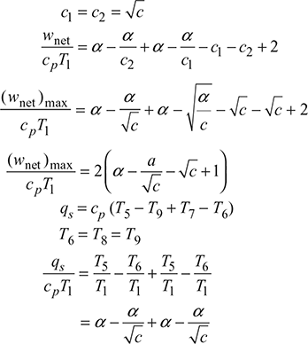
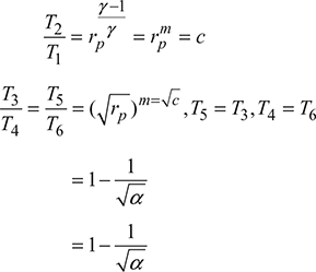
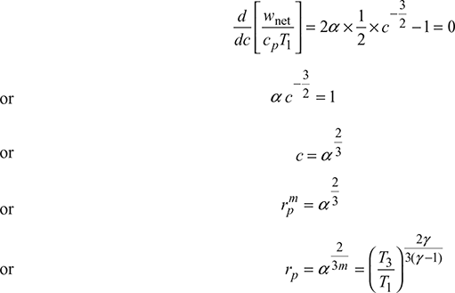
In a Brayton cycle, the pressure ratio in the compressor is rp. The minimum and maximum temperatures are T1 and T3. The air is expanded in two stages, each turbine having the same pressure ratio, with reheat to T3 between the stages. Show that the specific work output will be maximum when 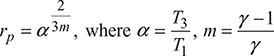
Solution
The T-s diagram is shown in Fig. 16.23.
Refer to Fig. 16.23.
Turbine work wt = cp (T3 − T4) + cp (T5 − T6)
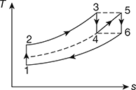
Figure 16.23 T-s diagram for Brayton cycle with two-stage turbine
= cp (T3 − T4) + cp (T3 − T6)
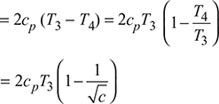
Compressor work 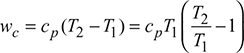
= cpT1 (c − 1)
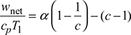
Specific work output 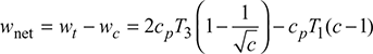
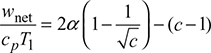
For maximum specific work output
Example 16.8
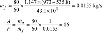
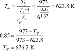
In a gas turbine, air is taken in at 1 bar pressure and 30°C. It is compressed to 6 bar with an isentropic efficiency of 87%. Heat is added by the combustion of fuel in combustion chamber to raise the temperature to 700°C. The efficiency of the turbine is 85%. The calorific value of fuel used is 43.1 MJ/kg. For an air flow of 80 kg/min, calculate (a) the air/fuel ratio of turbine gases, (b) the final temperature of exhaust gases, (c) the net power developed, and (d) the overall thermal efficiency of plant.
Assume cpa = 1.005 kJ/kgK, γa = 1.4, cpg = 1.147 kJ/kgK, γg = 1.33.
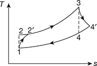
Figure 16.24 T-s diagram for gas turbine with machine efficiencies
Solution
The T-s diagram is shown in Fig. 16.24.
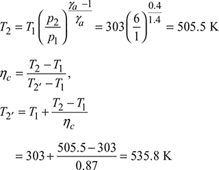
p1 = 1 bar, T1 = 273 + 30 = 303 K
p2 = 6 bar, ηc = 0.87, T3 = 273 + 700 = 973 K
ηt = 0.85, CV = 43.1 MJ/kg
Example 16.9
In a gas turbine plant, air enters the compressor at 1 bar and 7°C. It is compressed to 4 bar with an isentropic efficiency of 82%. The maximum temperature at the inlet to the turbine is 800°C. The isentropic efficiency of turbine is 85%. The calorific value of fuel used is 43100 kJ/kg. The heat losses are 15% of the calorific value. Calculate (a) the compressor work, (b) the heat supplied, (c) the turbine work, (d) the net work, (e) the thermal efficiency, (f) the air-fuel ratio, (g) the specific fuel consumption, and (h) the ratio of compressor to turbine work. Assume cpa = 1.005 kJ/kgK, γa = 1.4, cpg = 1.147 kJ/kgK, γg = 1.33.
Solution
p1 = 1 bar, T1 = 280 K, ηc = 0.82, p2 = 4 bar, T3 = 1073 K, ηt = 0.85, ηcomb = 0.85.
The T-s diagram is shown in Fig. 16.25.
Refer to Fig 16.25
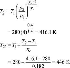
- The compressor work wc = cpa (T2′ − T1) = 1.005 (446 − 280) = 166.82 kJ/kg
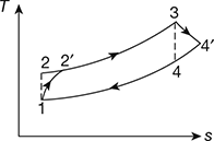 Figure 16.25 T-s diagram for gas turbine with machine efficiencies
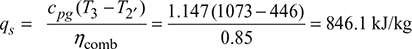
 - The heat supplied
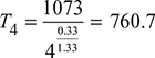 T4′ = T3 − ηt (T3 − T4) = 1073 − 0.85 (1073 − 760.7) = 807.5 K The turbine work wt = cpg (T3 − T4′) = 1.147 (1073 −807.5) = 304.53 kJ/kg
 - The net work output wnet= wt − wc = 304.153 −166.83 = 137.7 kJ/kg
- The thermal efficiency
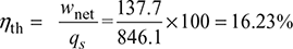
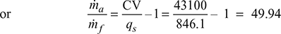
- ṁf × C.V. (1 – 0.15) = (ṁa + ṁf ) Q × ηcomb
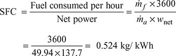
- The specific fuel consumption
Example 16.10
In a closed circuit gas turbine plant, the working fluid at 38°C is compressed with an adiabatic efficiency of 82%. It is then heated at constant pressure to 650°C. The fluid expands down to initial pressure in a turbine with an adiabatic efficiency of 80%. The pressure ratio is such that work done per kg is maximum. cpa = 1.005 kJ/kgK, cpg = 1.147 kJ/kgK. Calculate the pressure ratio for maximum work output and the corresponding cycle efficiency.
Solution
Refer to Fig 16.25.
For maximum specific work,
Example 16.11
A constant pressure closed cycle turbine plant works between a temperature range of 800°C and 30°C. The isentropic efficiencies of compressor and turbine are 80% and 90%, respectively. Find the pressure ratio of the cycle for maximum thermal efficiency and maximum specific output of the cycle.
Solution
T1 = 273 + 30 = 303 K, T3 = 273+ 800 = 1073 K, ηc = 0.8, ηt = 0.9
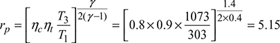
Pressure ratio for maximum specific output
Pressure ratio for maximum thermal efficiency 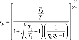
Example 16.12
A gas turbine plant operates between 5°C and 839°C. Find the following:
- Pressure ratio at which cycle efficiency equals to Carnot cycle efficiency
- Pressure ratio at which maximum work is obtained
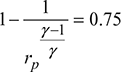
- Efficiency corresponding to maximum work output
Solution
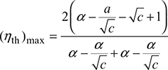
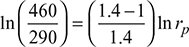
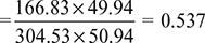
The efficiency of Carnot cycle ![]()
For simple gas turbine cycle, 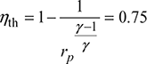
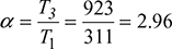
 or
or 
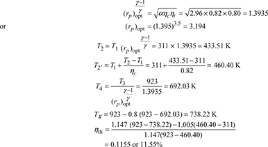
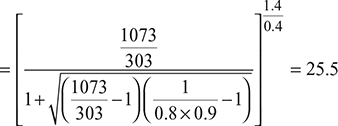
 For maximum work output
 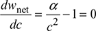 or
or 
Example 16.13
A simple open cycle gas turbine has a compressor turbine and a free power turbine. It develops electrical power output of 250 MW. The cycle takes in air at 1 bar and 288 K. The total compressor pressure ratio is 14. The turbine inlet temperature is 1500 K. The isentropic efficiency of compressor and turbine are 0.86 and 0.89, respectively. The mechanical efficiency of each shaft is 0.98. Combustion efficiency is 0.98 while combustor pressure loss is 0.03 bar. The alternator efficiency is 0.98. Take calorific value of fuel equal to 42,000 kJ/kg, cpa = 1.005 kJ/kgK and cpg = 1.15 kJ/kgK. Calculate (a) the air-fuel ratio, (b) the specific work output, (c) the specific fuel consumption, (d) the mass flow rate of air, and (e) the thermal efficiency of the cycle.
Solution
p1 = 1 bar, T1 = 288 K, p2 = 14 bar, p3 = 14 − 0.03 = 13.97 bar, T3 = 1500 K, P = 250 kW, ηc = 0.86, ηt = 0.89, ηmech = 0.98, ηcomb = 0.98, ηa = 0.98, CV = 42,000 kJ/kg, cpa = 1.005 kJ/kgK, cpg = 1.15 kJ/kgK
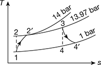
Figure 16.26 T-s diagram for gas turbine with pressure loss in combustion chamber
The T-s is shown in Fig. 16.26.
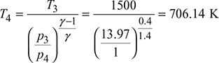
T2 = 288 (14)0.4/1.4 = 612.15 K
Compressor efficiency,
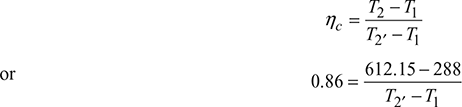
or T2′ − T1 = 376.92 K
or T2′ = 664.92 K
Turbine efficiency,
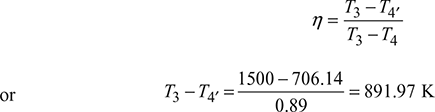
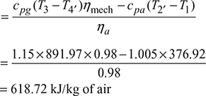
Actual net work done, wnet = Turbine work, wt − Compressor work, wc
qe = cpg ( T3 − T2′)
= 1.15 (1500 − 664.92) = 960.34 kJ/kg
Actual heat supplied,

- Air/fuel ratio,
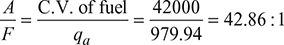
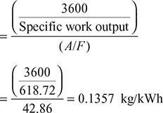
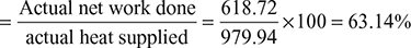
- Specific work output = 618.72 kJ/kg of air.
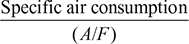
- Specific fuel consumption =
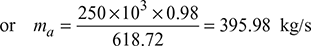
- Mass flow rate of air, ma × Specific work output= Electric power developed × Alternator efficiency
- Thermal efficiency of the cycle
Example 16.14
An open cycle gas turbine employs a regenerative arrangement. The air enters the compressor at 1 bar and 288 K and is compressed to 10 bar with a compression efficiency of 85%. The air is heated in the regenerator and the combustion chamber till its temperature is raised to 1700 K and during the process pressure falls by 0.2 bar. The air is then expanded in the turbine and passes to regenerate which has 75% effectiveness and causes a pressure drop of 0.2 bar. The isentropic efficiency of the turbine is 86%. By sketching the gas turbine system and showing the process on T-s diagram, calculate the thermal efficiency and the power output if mass flow rate of air is 100 kg/s. Take mechanical and alternator efficiency as 98% each. Take cpg = 1.15 kJ/kgK and cpa = 1.005 kJ/kgK.
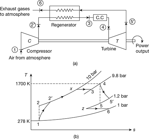
Figure 16.27 Open cycle gas turbine: (a) Gas turbine system, (b) T-s diagram
Solution
The gas turbine system and T-s diagram are shown in Fig. 16.27.
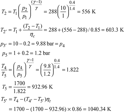
Work consumed by the compressor,
wc = cpa (T2′ − T1)
= 1.005 (603.3 − 288) = 316.876 kJ/kg
wt = cpg (T4 − T5′) = 1.15(1700 − 1040.34)
= 758.61 k/kg
Net work done = wt – wc = 758.61 − 316.876 = 441.73 kJ/kg
Regenerator effectiveness, ![]()
T3 = 0.75(1040.34 − 603.3) + 603.3 = 931.08 K
Heat supplied = cpa (T4 − T3) = 1.005(1700 − 931.08) = 772.76 kJ/kg
Thermal efficiency = ![]()
Power developed = 100 × 441.73 × 0.98 × 0.98 = 42423.75 kW
Example 16.15
Air enters the compressor of a gas turbine at 100 kPa, 300 K with a volumetric flow rate of 5 m3/s. The air is compressed in two stages to 1200 kPa with intercooling to 300 K between stages at a pressure of 350 kPa. The turbine inlet temperature is 1400 K and the expansion occurs in two stages with reheat to 1340 K between the stages at a pressure of 350 kPa. The compressor and turbine stage efficiencies are 87% and 85%, respectively. Draw the schematic diagram of the cycle and indicate the process on T-s diagram. Determine (a) the thermal efficiency of the cycles, (b) the back work ratio, (c) the net power developed in kW. Assume effectiveness of the regenerator as 80% and cp = 1.0045 kJ/kgK for air and gas.
Solution
The schematic diagram of the cycle and T-s diagram are shown in Fig. 16.28.
p1 = pa = 100 kPa, T1 = 300 K, V̇1 = 5 m3/s, p2 = p3 = p7 = p8 = 350 kPa,
p4 = p6 = 1200 kPa, T1 = T3 = 300 K, T6 = 1400 K, T8 = 1340 K,
ηc1 = ηc2 = 0.87, ηt1 = ηt2, ɛ = 0.85, cpa = cpg 1.0045 kJ/kgK
Compressor 1st stage:
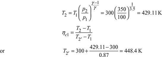
Work done, wc1 = cpa (T2′ − T1) = 1.0045 (448.4 − 300) = 149.07 kJ/kg
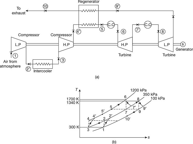
Figure 16.28 Gas turbine with intercooling, reheating, and regeneration: (a) Gas turbine system, (b) T-s diagram
Compressor 2nd stage:
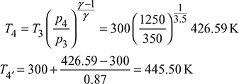
Work done, wc2 = cpa (T4′ − T3) = 1.0045 (445.50 − 300) = 146.16 kJ/kg
Total compressor work, wc = wc1 + wc2 = 295.23 kJ/kg
Turbine Ist stage:
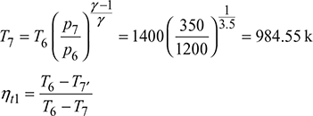
or T7′ = 1400 − 0.85 (1400 − 984.55) = 1046.87 K
Work done, wt1 = cpg (T6 − T7′) = 1.0045 (1400 −1046.87) = 354.72 kJ/kg
Turbine 2nd stage:
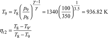
or T9′ = 1340 − 0.85 (1340 − 936.82) = 997.3 K
Work done, wt2 = cpg (T8 − T9′) = 1.0045 (1340 − 997.3) = 344.24 kJ/kg
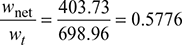
Total turbine work wt = wt1 + wt2 = 698.96 kJ/kg
Net work wnet = wt – wc = 698.96 − 295.23 = 403.73 kJ/kg
Regenerator effectiveness, 
or ![]()
or T5′ = 886.94 K
Heat supplied, qs = cpg [(T6 − T5′) + (T8 − T7′)]
= 1.0045 [(1400 − 886.94) + (1340 − 1046.87)]
= 809.82 kJ/kg
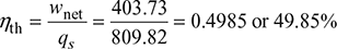
- Thermal efficiency,
- Work ratio =
- p1V̇1 = ṁRT1or
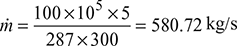 Power developed = ṁ × wnet = 580.72 × 403.73 = 234454 kW
Example 16.16
Air enters the compressor of a gas turbine plant operating on Brayton cycle at 1 bar, 27°C. The pressure ratio in the cycle is 6. If Wt = 2.5 Wc, where Wt and Wc are the turbine and compressor work, respectively, calculate the maximum temperature and the thermal efficiency of the cycle. Take γ = 1.4.
Solution
p1 = 1 bar, T1 = 27 + 273 = 300 K, p2 = 6 bar, γ = 1.4
Refer to Fig. 16.4, we get
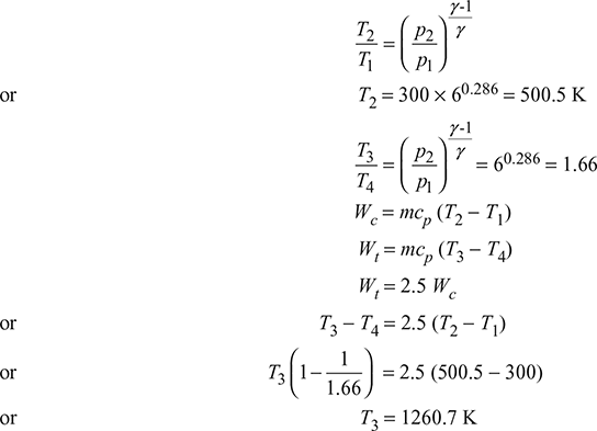
Thermal efficiency = ![]()
Example 16.17
In an air-standard regenerative gas turbine cycle, the pressure ratio is 5. Air enters the compressor at 1 bar, 300 K and leaves at 490 K. The maximum temperature in the cycle is 1000 K. If the effectiveness of the regenerator and the isentropic efficiency of the turbine are each 80%, determine the cycle efficiency. Assume γ =1.4 for air.
Solution
The cycle on the T-s diagram is shown in Fig. 16.29 assuming compressor efficiency to be 100%.
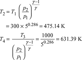
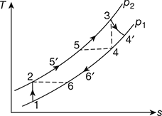
Figure 16.29 T-s diagram for gas turbine with regeneration
Turbine efficiency, = ![]()
or ![]()
or T4′ = 705.11 K
Regenerative effectiveness = ![]()
or ![]()
or T5′ = 659.116 K
wc = cp (T2 − T1) = 1.005 × (475.14 − 300)
= 176.01 kJ/kg
wt = cp (T3 − ![]() ) = 1.005 (1000 − 705.11)
) = 1.005 (1000 − 705.11)
= 296.36 kJ/kg
Net work, wnet = wt − wc = 296.36 − 176.01
= 120.35 kJ/kg
Heat supplied, qs = cp (T3 − T5′)
= 1.005 × (1000 − 659.116) = 342.58 kJ/kg
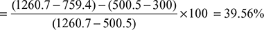
Thermal efficiency = ![]()
Leave a Reply