The steam supply to a steam engine is at 15 bar dry and saturated. The condenser pressure is 0.4 bar. Calculate the Rankine efficiency of the cycle. Neglect pump work.
Solution
Given: p1 = 15 bar, p2 = 0.4 bar, x1 = 1.0
From steam tables at 15 bar, h1 = hg = 2789.9 kJ/kg, s1 = sg = 6.4406 kJ/kg.K
| At 0.4 bar, | hf 2 = 317.7 kJ/kg, | hfg2 = 2319.2 kJ/kg |
| sf 2 = 1.0261 kJ/kg.K | sfg2 = 6.6448 kJ/kg.K |
For isentropic expansion of steam,
s1 = s2 = sf 2 + x2 sfg2
6.4406 = 1.0261 + x2 × 6.6448
x2 = 0.815
h2 = hf 2 + x2 hfg2 = 317.7 + 0.815 × 2319.2 = 2207.8 kJ/kg

Example 5.2
A simple Rankine cycle works between 28 bar and 0.06 bar. The initial condition of steam is dry and saturated. Calculate the cycle efficiency, work ratio and specific steam. consumption.
Solution
Given: p1 = 28 bar, x1 = 1.0 bar, p2 = 0.06 bar
The T–s diagram for the cycle is shown in Fig. 5.16.
From steam tables:
| At 28 bar, | h1 = 2802.0 kJ/kg, | s1 = 6.2101 kJ/kg.K |
| At 0.06 bar, | hf 2 = hf 3 = 151.5 kJ/kg, | hfg2 = 2415.9 kJ/kg |
| sf 2 = 0.521 kJ/kg.K | sfg2 = 7.809 kJ/kg.K | |
| vf 3 = vf 2 = 0.001 m3/kg |

Figure 5.16
For isentropic process 1-2, we have
s1 = s2 = sf 2 = x2 sfg 2
6.2104 = 0.521 + x2 × 7.809
x2 = 0.728
h2 = hf 2 + x2 hfg2 = 151.5 + 0.728 × 2415.9 = 1910.27 kJ/kg
Engine work, wc = h1 − h2 = 2802.0 − 1910.27 = 891.73 kJ/kg
Pump work, wp = hf 4 − hf 3 = vf 3 (p1 − p2)
= 0.001 (28 − 0.06) × 102 = 2.79 kJ/kg
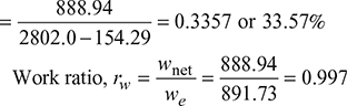
Net engine work, wnet = wc − wp = 891.73 − 2.79 = 888.94 kJ/kg
hf4 = hf3 + wp = 151.5 + 2.79 = 154.29 kJ/kg
Rankine efficiency, ![]()
Specific steam consumption, ![]()
Example 5.3
A single cylinder double acting engine has a bore of 250 mm and a stroke 300 mm. Steam is admitted at a pressure of 1.3 MPa. Cut-off occurs at 30% of stroke and the exhaust pressure is 0.12 MPa. The diagram factor is 0.82 and the mechanical efficiency is 80%. The engine runs at 150 rpm. Calculate of the power developed.
Solution
Given: D = 0.5 m, L = 0.3 m, p1 = 1.3 MPa, ![]() , Kd = 0.82
, Kd = 0.82
ηmech = 0.8, pb = 0.12MPa, N =150 rpm
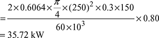
Mean effective pressure,![]()
Brake power developed, 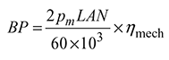
Example 5.4
Dry saturated steam at 0.9 MPa is supplied to a single cylinder double acting steam engine developing 20 kW at 240 rpm. The exhaust is 0.15 MPa. Cut-off takes place at 40% of stroke. The diagram factor is 0.8 and stroke to bore ratio is 1.25. Assuming hyperbolic expansion determine (a) bore and stroke of engine, and (b) steam consumption per hour.
Solution
Given: p1 = 0.9 MPa, IP = 20 kW, N = 240 rpm, pb = 0.15 MPa

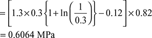
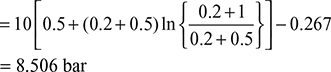
Mean effective pressure,![]()
= [0.9× 0.4(1+ ln 2.5) − 0.15]× 0.8
= 0.4319 MPa
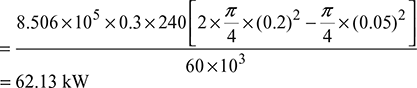
Power developed, ![]()
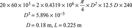
Steam consumption/h ![]()
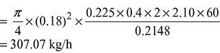
Specific volume of dry saturated steam at 0.9 MPa = 0.2148 m3/kg from steam tables.
Example 5.5
A single cylinder double acting steam engine receives steam at 1.0 MPa and exhaust at 0.055 MPa. The dryness of inlet steam is 96%. The power developed by the engine when running at 220 rpm is 45 kW, with steam consumption of 450kg/h. The engine bore is 0.25 m and stroke is 0.375 m. The expansion ratio is 6. Calculate the diagram factor and the indicated thermal efficiency of the engine.
Solution
Given: p1 = 1.0 MPa, pb = 0.055 MPa, x = 0.96, IP = 45 kW, N = 220 rpm, ms = 450 kg/h, D = 0.25 m, L = 0.375 m, r = 6
Theoretical m.c.p. pmt ![]()
Actual m.e.p pm = pmt × Kd = 0.4103× Kd
Power developed, IP ![]()

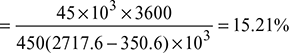
Enthalpy of steam at 1 MPa and 0.96 dry, from steam tables,
h1 = hf 1 + x hfg = 762.6 + 0.96 × 2013.6 = 2717.6 kJ/kg
Enthalpy of water at exhaust pressure of 0.055 MPa, hf 3 = 350.6 kJ/kg
Indicated thermal efficiency 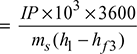
Example 5.6
A single cylinder double acting condensing type steam engine delivers 20 kW brake power at 240 rpm. The diameter and stroke of the engine are 0.2 m and 0.3 m respectively. The steam is supplied at 10 bar and cut-off takes place at 50% of stroke. The condenser vacuum is 56 cm of Hg while the barometer reads 76 cm of Hg. Mechanical efficiency is 80% clearance is 20 % of stroke and piston rod diameter is 5 cm. Determine the actual mean effective pressure and diagram factor.
Also determine the specific steam consumption on I.P. basis by neglecting clearance and piston rod area.
Solution
Given: BP = 20 kW, N = 240 rpm, D = 0.2 m, d = 0.5 m,
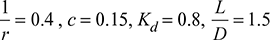
L = 0.3 m p1 = 10 bar, ![]() , c = 0.2, ηmech = 0.8 x = 0.95
, c = 0.2, ηmech = 0.8 x = 0.95

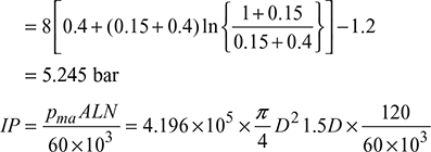
Indicated, m.e.p 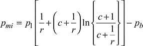
Indicated power, ![]()
Actual m.e.p., ![]() bar
bar
Diagram factor,![]()
Neglecting clearance and piston rod area, volume of steam supplied per revolution of engine at 10 bar.

supplied per hour ![]()
Steam supplied in kg/h ![]()
where vg = 0.198m3/kg at 10 bar from steam tables

Specific steam consumption on IP basis, ![]()
Example 5.7
Calculate the diameter and stroke of a single cylinder double acting steam engine developing 50 kW power at 120 rpm with mechanical efficiency of 80%. The steam is supplied at 8 bar pressure and back pressure of the engine is 1.2 bar. Cut-off takes place at 40% of the stroke and clearance is 15% of stroke volume.
Assume diagram factor 0.8, and stroke to bore ratio as 1.5.
Solution
Given: BP = 560 kW, N = 120 rpm, ηmech = 0.8, p1 = 8 bar, pb = 1.2 bar,
Indicated, m.e.p 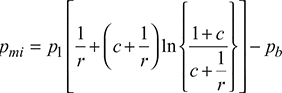
62.5 = 9.8874 × 10² × D3
D = 0.398 m or 39.8 cm
L = 1.5 × 0.398 = 59.75 cm
Example 5.8
The steam enters a steam engine at 15 bar and exhausts at 1.5 bar.
The steam supply is cut-off at 40% of the stroke. The clearance volume is 5% of the swept volume. Calculate the mean effective pressure.
Solution
Given: p1 = 15 bar, pb = 1.5 bar, ![]() = 0.4, c = 0.05
= 0.4, c = 0.05
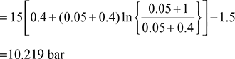
Indicated, m.c.p 
Example 5.9
In a steam engine, the clearance volume is 5% of swept volume and the back pressure is 1.15 bar. If the compression is at 0.3 of the stroke, find the pressure .at the end of compression stroke.
Find also the mean effective pressure, if the steam supply pressure is 13.7 bar and cut-off occurs at 40% of stroke.
Solution
The p-v diagram is shown in Fig. 5.17
Given: c = 0.05, p1 = 13.7 bar, pb = 1.15 bar, ![]() = 0.4, V5 − Vc = 0.3 Vs, a= 0.3 =
= 0.4, V5 − Vc = 0.3 Vs, a= 0.3 = ![]()
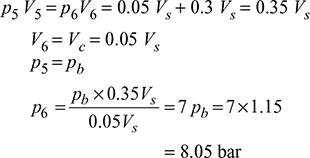

Figure 5.17

Example 5.10
The area of indicator diagram 25 cm2. The swept volume is 0.15 cm2. Calculated the theoretical mean effective pressure. The indicator diagram is drawn to the following scales:
1 cm = 1 bar along the pressure axis
1 cm = 0.02 m3 along the volume axis
Spring constant = 1 bar/cm.
Solution
Given: A1 = 25 cm2, Vs = 0.15 cm2, S = 1 bar/cm
M.E.P., 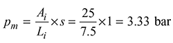
Example 5.11
Find the diagram factor for steam engine with the following data.
Inlet pressure = 10 bar
Back pressure = 1 bar
Expansion ratio = 3
Area of indicator diagram = 12.1 cm2
Length of indicator diagram = 7.5 cm
Pressure scale = 3 bar/cm
Solution
Given: p1 = 10 bar, pb = 1 bar, r = 3, A1 = 12.1 cm2, L1 = 7.5 cm
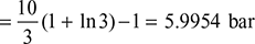
Theoretical m.c.p.,![]()
Actual m.e.p.,![]()
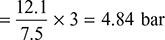
Diagram factor,![]()
Example 5.12
Determine the brake power of a simple double acting steam engine having 400 mm diameter and 500 mm stroke length operating at 350 rpm. The initial and back pressure of steam are 9.5 bar and 1.5 bar respectively. The mechanical efficiency is 80% and the expansion ratio is 2.5.
Solution
Given: D = 0.4 m, L = 0.5 m, N = 350 rpm, p1 = 9.5 bar, pb = 1.5 bar
Indicated m.c.p.,![]()
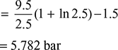

B.P = IP × ηmech = 423.843 × 0.8 = 339.074 kW
Example 5.13
A double acting steam engine has a cylinder bore 200 mm stroke 300 mm and cut-off takes place at 0.4 stroke. The steam admission and the exhaust pressure are 7 bar and 0.38 bar respectively. If the diagram factor is 0.8, calculate the indicated power at 200 rpm. Neglect clearance and assume hyperbolic expansion.
Solution
Given: D = 0.2 m, L = 0.3 m, ![]() = 0.4, p1 = 7 bar, pb = 0.38 bar, Kd = 0.8, N = 200 rpm
= 0.4, p1 = 7 bar, pb = 0.38 bar, Kd = 0.8, N = 200 rpm
Theoretical m.e.p., ![]()
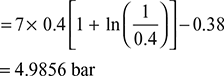
Actual m.e.p.. pma = pmt × Kd = 4.9856 × 0.8 = 3.9885 bar
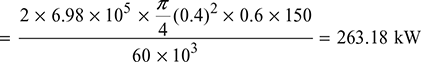
Power developed, ![]()
= 25.06 kW
Example 5.14
The following readings were taken during the test at full load on a single cylinder, double acting, condensing type, throttle governed steam engine
Diameter of cylinder = 400 mm
Stroke of engine = 600 mm
Cut-off = 50% of stroke
Pressure of steam supplied = 11 bar
Back pressure = 0.8 bar
Brake wheel diameter = 4.5 m
Net load on the bake = 4900 N
Speed of engine = 150 rpm
Diagram factor = 0.82
Find the indicated power, brake power and mechanical efficiency of the engine.
Solution
Given: D = 0.4 m, L = 0.6 m, ![]() = 0.5, p1 = 11 bar, pb = 0.8 bar, Db = 4.5 m, Wnet = 4900 N, N = 150 rpm, Kd = 0.82
= 0.5, p1 = 11 bar, pb = 0.8 bar, Db = 4.5 m, Wnet = 4900 N, N = 150 rpm, Kd = 0.82
= 11 × 0.5 (1 + ln 2) − 0.8 = 8.5123 bar
Actual m.e.p., pma = pml × Kd = 8.5123 × 0.82 = 6.98bar
Indicated Power, ![]()
Brake power, ![]()
Mechanical efficiency, ![]()
Leave a Reply