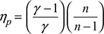
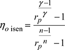
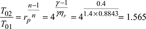
An axial compressor is fitted with half-reaction blading, the blade inlet and outlet angles being 50° and 15° when measured from the axial direction. The mean diameter of a certain blade pair is 85 cm and the rotor runs at 5500 rpm. Calculate the necessary isentropic efficiency of the stage if the pressure ratio of compression is to be 1.4 and the inlet air temperature is 25°C. Take cp =1.005 kJ/kg. K, γ = 1.4.
Solution
β1 = 50°, β2 = 15°, vf1 = vf2 = vf, α1 = 15°, α2 = 50°
Mean blade speed,
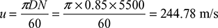
From the velocity triangles, (Fig. 15.11)
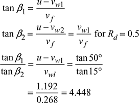
vw1 = 0.1826 u
vw2 = 0.8164 u
Δvw = vw2 − vw1 = 0.6328 u = 0.6328 × 244.78 = 155 m/s
Work done/kg, wa = u × ∆vw = 244.78 × 155 = 37940.9 N.m/kg
Isentropic work, wisen = cp (T2 − T1)
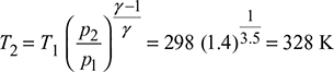
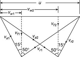
Figure 15.11 Velocity diagrams for axial flow compressor
wisen = 1.005 (328 − 298) = 30.15 kJ/kg
Isentropic efficiency,
Example 15.2
An axial flow compressor comprises a number of similar stages with equal work done per stage, and the velocity of flow is uniform throughout the compressor. The following data is given:
Overall stagnation pressure ratio = 4
Stagnation inlet temperature = 330 K
Relative air angle at rotor inlet = 130°
Relative air angle at rotor outlet = 100°
Blade velocity = 180 m/s
Degree of reaction = 0.5
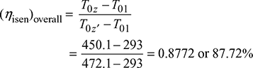
Overall stagnation adiabatic efficiency = 0.86
Calculate (a) the stagnation outlet temperature, and (b) number of stages.
Solution
The velocity diagrams are shown in Fig. 15.12.
Stagnation adiabatic efficiency,
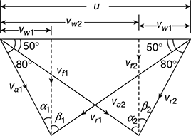
Figure 15.12 Velocity diagrams for axial flow compressor
T02′ = 516.5 K
For degree of reaction = 0.5, the velocity diagrams are similar.
∴ u − vw2 = vw1
vw1 = 0.1737 u
vw2 = u − vw1 = 0.8263 u
Δvw = vw2 − vw1 = 0.6526 u
Work done per stage = u · ∆vw = 180 × 0.6526 × 180 = 21144 N.m/kg
Total work = cp (T02 − T01) = 1.005(490.38 − 330) = 161.182 kJ/kg
Number of stages = ![]() = 7.62 = 8
= 7.62 = 8
Example 15.3
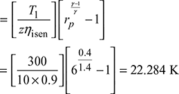
Air at a temperature of 300 K enters a 10-stage axial flow compressor at the rate of 3.5 m/s. The pressure ratio is 6.0 and the isentropic efficiency is 90%. The process is adiabatic and the compressor has symmetrical stages. The axial velocity is uniform across the stage and equals to 120 m/s and the mean blade speed of each stage is 200 m/s. Assume that the temperature change is same in each stage.
Determine the direction of the air at entry to and exit from the rotor and the stator blades. Also, find the power given to the air. Take cp = 1.005 kJ/kg.K and γ = 1.4.
Solution
The velocity diagrams are shown in Fig. 15.13.
z = 10, T1 = 300 K, ṁ = 3.5 kg/s, rp = 6, ηi = 0.9,
vf = 120 m/s, u = 200 m/s
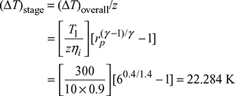
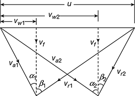
Figure 15.13 Velocity diagrams for axial flow compressor
Increase in temperature per stage,
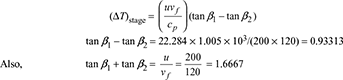
tan β1 = 1.2999, β1 = 52.43°, β2 = 20.14°
Power supplied = zṁcp (∆T)stage = 10 × 3.5 × 1.005 × 22.284 = 783.84 kW
Example 15.4
In an axial flow air compressor: u = 250 m/s, vf = 200 m/s, α1 = 50°, α2 = 15° and ρ = 1 kg/m3. Determine (a) the pressure rise, and (b) the work done per kg of air.
Solution
- Pressure rise through a moving blade ring,
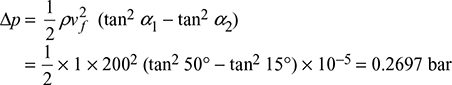
- Work done per kg of air,w = u (vw1 − vw2) = uvf (tan α1 − tan α2)= 250 × 200 (tan 50° − tan 15°) × 10−3 = 46.19 kW
Example 15.5
An axial flow air compressor having eight stages and 50% degree of reaction compresses air in the pressure ratio of 4.5 : 1. Air enters the compressor at 27°C and flows through it with a constant speed of 100 m/s. The moving blades of compressor rotate with a mean speed of 200 m/s. The isentropic efficiency of the compressor is 85%. Calculate (a) the work done on the compressor and (b) blade angles. Take γ = 1.4 and cp = 1.005 kJ/kg.K for air.
Solution
z = 8, Rd = 0.5, rp = 4.5, T1 = 273 + 27 = 300 K, vf = 100 m/s, u = 200 m/s, ηisen = 0.85
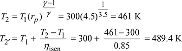
- Work required per kg of air,w = cp (T2′ − T1) = 1.005 (489.4 − 300) = 190.36 kJ/kg
- Total work done = zu (vw2 − vw1) = zu vf (tan α2 − tan α1)190.36 = 8 × 200 × 100 (tan α2 − tan α1) × 10−3tan α2 − tan α1 = 1.1897For Rd = 0.5, α1 = β2 and α2 = β1∴ 1.1897 = tan β1 − tan β2or tan β1 − tan α1= 1.1897Now, u = vf (tan α1 + tan β1)
 Adding the above two equations, we get2 tan β1 = 3.1897or tan β1= 1.5949or β1 = 57.9° = α2tan α1 = tan β1 − 1.1897 = 0.4052or α1 = 22° = β2
Example 15.6
The overall isentropic efficiency of an axial flow air compressor is 83%. It draws air at 25°C and 1 bar and compresses to 4 bar. Assuming 50% degree of reaction, blade velocity 180 m/s, exit angle from stator (α1) = 15°, inlet angle to rotor (β1) = 45° and work input factor as 0.80, calculate the flow velocity and the number of stages.
Solution
ηisen = 0.83, T1 = 273 + 25 = 298 K, p1 = 1 bar, p2 = 4 bar, Rd = 0.5, α1 = 15°, β1 = 45°, u = 180 m/s, ϕw = 0.80
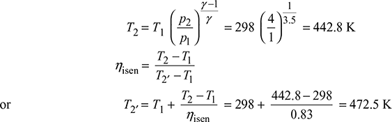
= cp (T2′ − T1) = 1.005 (472.5 − 298) = 175.37 kJ/kg
From inlet velocity triangle (Fig.15.13), we have
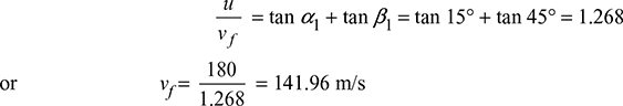
For Rd = 0.5, α2 = β1 = 45° and α1 = β2 = 15°
vw2 = vf tan α2 = 141.96 tan 45° = 141.96 m/s
vw1 = vf tan α1 = 141.96 tan 15° = 38.04 m/s
Work done per kg per stage = ϕwu(vw2 − vw1)
= 0.80 × 180 (141.96 − 38.04) × 10−3 = 14.965 kJ/kg
Number of stages, z = ![]() = 11.72 = 12
= 11.72 = 12
Example 15.7
In a 10-stage axial flow air compressor, the overall stagnation pressure ratio is 4 : 1 with an overall isentropic efficiency of 90%. The inlet stagnation temperature and pressure are 293 K and 1 bar. The work is divided equally between the stages. The mean blade speed is 180 m/s and 50% reaction blading are used. The flow velocity throughout the compressor is 90 m/s. Calculate (a) the blade angles, and (b) the power required.
Solution
z = 10, rop = 4, ηisen = 0.9, T01 = 293 K, p01 = 1 bar, u = 180 m/s, Rd = 0.5, vf = 90 m/s
- For Rd = 0.5, α1 = β2 and α2 = β1With isentropic compression, the temperature of air leaving the compressor is,
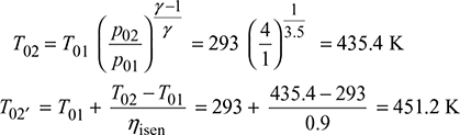 Work required by the compressor = cp (T02′ − T01) = 1.005 (451.2 − 293) = 159 kJ/kg= zu (vw2 − vw1)= zuvf (tan α2 − tan α1)
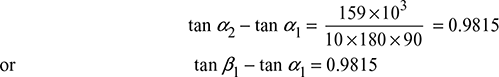 From inlet velocity triangle, we have,
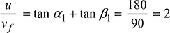 Adding the above two equations, we get2 tan β1 = 2.9815or tan β1 = 1.4908or β1 = 56.15° = α2tan α1 = 2 − 1.4908 = 0.5092or α1 = 26.98° = β2
 - Power required = ṁcp(T02′ − T01) = 1 × 1.005 (451.2 − 293) = 159 kW
Example 15.8
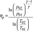
The overall stagnation pressure ratio and isentropic efficiency for an axial flow air compressor are 5 and 82%, respectively. The inlet stagnation pressure and temperature are 1 bar and 303 K. The mean blade speed is 200 m/s and degree of reaction is 0.5. The relative air angles are 12° and 30° at the rotor inlet and outlet, respectively. The work input factor is 0.9. Calculate (a) the stagnation polytropic efficiency, (b) the number of stages, (c) the inlet temperature and pressure, and (d) the blade height in the first stage if the hub-tip ratio is 0.42 and mass flow rate is 20 kg/s.
Solution
rop = 5, ηisen = 0.82, p01 = 1 bar, T01 = 303 K, u = 200 m/s, Rd = 0.5, β1 = 30° = α2, β2 = 12° = α1, ϕw = 0.9, ṁ = 20 kg/s, hub-tip ratio = 0.42.
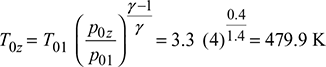
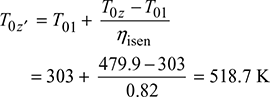 Polytropic efficiency,
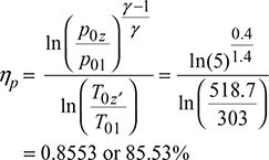
- From the inlet velocity triangle (Fig. 15.13), we have
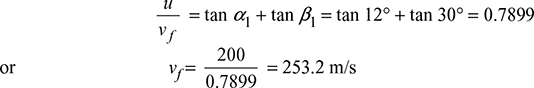 vw2 = vf2 tan α2 = 253.2 tan 30° = 146.2 m/svw1 = vf tan α1 = 253.2 tan 12° = 53.8 m/sWork consumed per stage = ϕw u(vw2 − vw1) = 0.9 × 200 (146.2 − 53.8) × 10−3 = 16.632 kJ/kgTotal work consumed by the compressor = cp (T0z′ − T01) = 1.005 (518.7 − 303) = 216.78 kJ/kgNumber of stages,
 = 258.86 m/sStatic temperature,
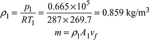 = 0.859 kg/m3m = ρ1A1vfor 20 = 0.859 × π
 [1 − (0.42)2] × 253.2or r1 = 0.1885 m or 188.5 mm
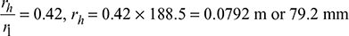
Example 15.9
A multistage axial flow air compressor delivers 25 kg/s of air. The inlet stagnation condition is 1 bar and 20°C. The power consumed by the compressor is 4500 kW. Calculate (a) the delivery pressure, (b) the number of stages, and (c) the overall isentropic efficiency of the compressor.
Assume that temperature rise in the first stage is 15° C, the polytropic efficiency of compression is 0.90 and the stage stagnation pressure ratio is constant.
Solution
ṁ = 25 kg/s, p01 = 1 bar, T01 = 273 + 20 = 293 K, P = 4500 kW, T02 = 293 + 15 = 308 K, np = 0.90
- Polytropic efficiency
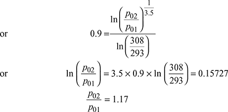 Power P = ṁcp (T0z′ − T01)or 4500 = 25 × 1.005 (T0z′ − 293)or T0z′ = 472.1 KAgain, polytropic efficiency can be expressed as
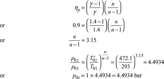
Example 15.10
An axial compressor receives 1000 m3/min of free air at 15°C and 0.9 bar. The blades are of aerofoil type having projected area and blade length as 19.25 cm2 and 6.75 cm, respectively. The blade ring mean diameter is 60 cm and the speed is 6000 rpm. On each blade ring, there are 50 blades and the blades occupy 10% of the axial area of flow. Value of CL and CD are 0.6 and 0.05 respectively at zero angle of incidence. Assuming isentropic compression, calculate the pressure rise per blade ring and the power input per stage. Assume axial inlet.
Solution
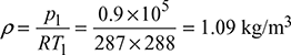
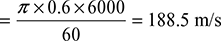
V̇ = 1000 m3/min, T1 = 273 + 15 = 288 K, p1 = 0.9 bar, A = 19.25 cm2, h = 6.75 cm, kb = 0.9, CL = 0.6, CD = 0.05, Dm = 60 cm, i = 50
Density of air,
Area across flow, Af = kb πDmh
= 0.9 × π × 0.6 × 6.75 × 10−2
= 0.1145 m2
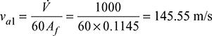
Blade velocity, ![]()
For axial inlet, va1 = vf = 145.55 m/s
The velocity triangle at inlet is shown in Fig. 15.14.
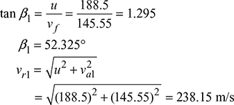
Figure 15.14 Velocity diagram for axial flow compressor
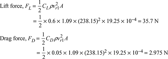
Power input per stage,
p = (FL cos β1 + FD sin β1) ui
= (35.7 cos 52.325° + 2.975 sin 52.325°) × 188.5 × 50 × 10−3
= 227.839 kW
Mass flow rate,
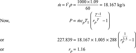
p2 = 0.9 × 1.16 = 1.044 bar
Pressure rise = p2 − p1 = 1.044 − 0.9 = 0.144 bar
Example 15.11
An axial flow compressor gives a pressure rise of 4 : 1 and the total head isentropic efficiency is 86%. Stagnation inlet temperature is 17°C. The inlet and outlet air angles from the rotor blades are 45° and 10°, respectively. The rotor and stator blades are symmetrical. The mean blade and axial velocity remain constant. Assuming blade speed of 220 m/s and work input factor 0.86, find the polytropic efficiency, number of stages required and Mach number. Take R = 287 J/kg.K.
Solution
rp = 4, ηo isen = 0.86, T01 = 273 + 17 = 290 K, α1 = 45°, α2 = 10°, u = 220 m/s, ϕw = 0.86
Polytropic efficiency,
Head isentropic efficiency,
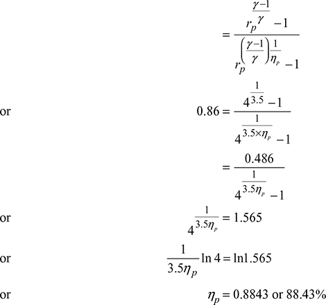
The velocity diagrams are shown in Fig. 15.15.
α1 = β2 = 10°, α2 = β1 = 45°
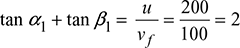
u = vf1 (tan α1 + tan β1)

Power required per kg of air = cp (T2 − T1) = ϕw uvf (tan α2 − tan α1)
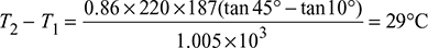
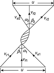
Figure 15.15 Velocity diagrams at inlet and outlet of vane
T02 = 290 × 1.565 = 453.86 K
Total temperature rise = T02 − T01
= 453.86 − 290 = 163.86°C
Number of stages, ![]()
From the inlet velocity diagram,
Example 15.12
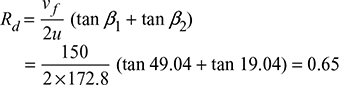
Air at 1.01325 bar and 288 K enters an axial flow compressor stage with an axial velocity of 150 m/s. There are no inlet guide vanes. The rotor stage has a tip diameter of 60 cm and a hub diameter of 50 cm and rotates at 100 rps. The air enters the rotor and leaves the stator in the axial direction with no change in velocity or radius. The air is turned through 30° as it passes through rotor.
Assuming constant specific heat and that air enters and leaves the blade at the blade angles, construct the velocity diagrams at mean diameter for this stage, and calculate (a) the mass flow rate, (b) the power required, and (c) the degree of reaction.
Solution
p1 = 1.01325 bar, T1 = 288 K, vf = 150 m/s, D2 = 60 cm, D1 = 50 cm, N = 100 rps, β2 − β1 = 30°
The velocity triangles are shown in Fig. 15.16.
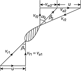
Figure 15.16 Velocity diagrams at inlet and outlet of vane
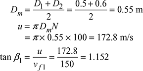
or β1 = 49.04°
β2 − β1 = 30° or β1 − β2 = 30°
or β2 = 19.04° or 79.04°
vf2 tan β2 = u + vw2
150 tan 19.04° = 51.77 < 172.8 m/s
∴ vw2 is −ve
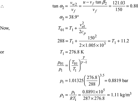
Volume flow rate,
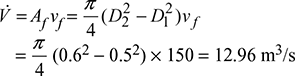
- Mass flow rate,ṁ = V̇ρ = 12.96 × 1.11 = 14.384 kg/s
- Power required,P = ṁuvf = 14.384 × 172.8 × 150 × 10−3 = 372.85 kW
- Degree of reaction,
Example 15.13
An axial flow compressor with pressure compression ratio 4 draws air at 20°C and delivers at 197°C. The mean blade speed and flow velocity are constant throughout the compressor. Assuming 50% reaction and blading velocity as 180 m/s, find the flow velocity and number of stages. Take work input factor = 0.82, α1 = 20°, β1 = 42°, cp = 1.005 kJ/kg K.
Solution
Given: rp = 4, T1 = 273 + 20 = 293 K, T2 = 273 + 197 = 470 K, u = u1 = u2 and vf1 = vf1 = vf, Rd = 0.5, u = 180 m/s, ϕw = 0.82, α1 = 20°, β1 = 42°, cp = 1.005 kJ/kg K
For 50% degree of reaction,
α2 = β1 = 42° and β2 = α1 = 20°
Work input factor,
Refer to Fig. 15.17
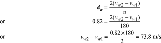
Δvw = vw2 − vw1 = vf (tan α2 − tan α1)
= vf (tan 42° − tan 20°) = 0.5364 vf
∴ 0.5364 vf = 73.8
Flow velocity, vf = 137.6 m/s
Work done per stage = u × ∆vw
= 180 × 73.8 = 13284 Nm/kg
Total work = cp (T2 − T1)
= 1.005 × 10³ (470 − 293) = 177885 Nm/kg
Number of stages, ![]()
= 13.39 ≃ 14
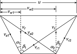
Figure 15.17 Velocity diagrams for axial flow compressor
Example 15.14
An eight-stage axial flow compressor provides an overall pressure ratio of 6: 1 with an overall isentropic efficiency 90% when the temperature of air at inlet is 20°C. The work divided equally between the stages. A 50% reaction design is used with a mean blade speed 188 m/s and a constant axial velocity 100 m/s through the compressor. Estimate the power required and the blade angles. Take cp = 1.005 kJ/kg.K and γ = 1.4.
Solution
Given: z = 8, pz/p1 = 6, (ηisen)0 = 0.9, T1 = 273 + 20 = 293 K, Rd = 0.5, u = 188 m/s, vf = 100 m/s
Refer to Fig. 15.18. 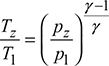
For Rd = 0.5, α1 = β2, α2 = β1
From Fig. 15.19, we have vw1 = vf1 tan α1 and vw2 = vf2 tan α2
Work done per kg of air, w = zu (vw2 − vw1)
= 150.4 (tan α2 − tan α1)
= 150.4 (tan β1 − tan α1)
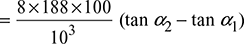
= cp (Tz′ − T1) = 0.24 × 4.187 (510.8 − 293) = 218.86
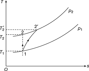
Figure 15.18 T-s diagram
Figure 15.19 Velocity triangles
∴ tan β1 − tan α1 = 1.455
After solving, we get
2 tan β1 = 3.335
or β1 = 59°
tan α1 = 1.88 − 1.6676 = 0.2124
or α1 = 12°
Power required = cp (Tz′ − T1) = 0.24 × 4.187 (510.8 − 293)
= 218.86 kW
Example 15.15
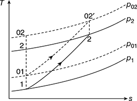
The first stage of an axial compressor is designed on free vortex principles with no inlet guide vanes. The rotational speed is 6000 rpm and the stagnation temperature rise is 20 K. The hub-tip ratio is 0.60, work done factor is 0.93 and isentropic efficiency of the stage is 0.89. Assuming an inlet velocity of 140 m/s and ambient conditions of 1.01 bar and 288 K, calculate (a) the tip radius and corresponding rotor air angles, if the Mach number relative to the tip is limited to 0.95, (b) the mass flow entering the stage, (c) the stage stagnation pressure ratio and power input, and (d) rotor air angles at the root section. Assume cp = 1.005 kJ/kgK and γ = 1.4.
Solution
Given: N = 6000 rpm, ![]() = 20 K,
= 20 K, ![]() = 0.6, ϕw = 0.93, (ηisen)stage = 0.89, va1 = 140 m/s, p1 = 1.01 bar, T1 = 288 K, M = 0.95, cp = 1.005 kJ/kg.K, γ = 1.4
= 0.6, ϕw = 0.93, (ηisen)stage = 0.89, va1 = 140 m/s, p1 = 1.01 bar, T1 = 288 K, M = 0.95, cp = 1.005 kJ/kg.K, γ = 1.4
With no inlet guide vanes, α1 = 0° and vf1 = va1 = 140 m/s, vw1 = 0
For free vortex flow = vw1 × rh = vw2 × rt
The velocity diagrams are as shown in the Fig. 15.20(a).
Also, vf 1 = vf 2 = vf
∴ va2 = va1 and β1 = β2
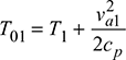
Figure 15.20 (a) Velocity diagrams, (b) T-s diagram for axial flow compressor
T02 = T01 (T02′ − T01) ×(ηisen)stage
= 297.75 + 20 × 0.89 = 315.55 K
- Mach number relative to tip, M = 0.95
 or vr2 = 333.1 m/s
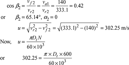 Tip diameter, Dt = 962 mmHub diameter, Dh = 0.6 Dt = 0.6 × 962 = 577.2 mm
- Density of air at inlet,
 Mass flow rate of air entering the stage,

- α1 = α2 = 0°, β1 = β2 = 65.14°
Example 15.16
An axial flow compressor has an overall pressure ratio of 4 and mass flow rate of 3 kg/s. If the polytropic efficiency is 88% and the stagnation temperature rise per stage must not exceed 25 K, calculate the number of stages required and pressure ratio of first and last stages. Assume equal temperature rise in all stages. If the absolute velocity approaching the last rotor is 165 m/s at an angle of 20° from the axial direction, the work done factor is 0.83, the velocity diagram is symmetrical and the mean diameter of last stage rotor is 18 cm, calculate the rotational speed and length of the last stage rotor blade inlet to the stage. Ambient conditions are 1.01 bar and 288 K.
Solution
Given: ![]() = 4, ṁa = 3 m/s, ηp = 0.88, (dT0η)stage ≤ 25K, (va1)z = 165 m/s, α1 = 20°, ϕw = 0.83, (dm)z = 0.18 m, p1 = 1.01 bar, T1 = 288 K
= 4, ṁa = 3 m/s, ηp = 0.88, (dT0η)stage ≤ 25K, (va1)z = 165 m/s, α1 = 20°, ϕw = 0.83, (dm)z = 0.18 m, p1 = 1.01 bar, T1 = 288 K
Refer to Fig. 15.21.
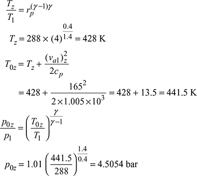
Now, (va1)1 = (va1)z = 165 m/s
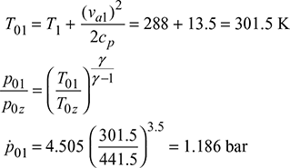
Pressure ratio of first and last stage,

or n = 1.48
∴ T0z′ = 301.5(3.8)0.48/1.48 = 464.9 K
Number of stages, ![]()
Actual stagnation temperature rise per stage
Hence O.K.
For symmetrical velocity diagram, α1 = β2 (see Fig. 15.22)
Work done per stage, w = cp × (dT ′0)stage × ϕw
= 1.005 × 23.4 × 0.83 = 19.519 kJ/kg
Also, w = (vw2 − vw1)u
= (v − 2vw1)u = (u − 2 × va1 sin α1)u
= (u − 2 × 165 sin 200)u = (u − 112.87)u
or u2 − 112.87 u = 19519
or u2 − 112.87 u − 19519 = 0
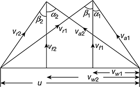
Figure 15.22 Symmetrical velocity diagrams
Area across flow, Af = πdmh
Density of air, ρ1 =  = 1.222 kg/m3
Velocity of flow, vf 1 = va1 cos α1 = 165 cos 20° = 155 m/s
ṁa = ρ1Af vf 1
3 = 1.222 × π × 0.18 × h × 155
h = 0.028 m or 2.8 cm
Length of last stage rotor blade, h = 2.8 cm.
Example 15.17
An axial-flow compressor employed in gas turbine plant delivers air at the rate of 300 kg/s and develops a total pressure ratio of 20. The inlet stagnation conditions are 1 bar and 300 K and the blade speed is kept at 200 m/s to minimise noise generation. The stage degree of reaction at the mean blade height is 50%. The axial velocity of flow is 160 m/s. The work done factor is 0.88. The hub-tip diameter ratio is 0.8. Assume actual temperature rise in each stage. Show the process on T–s diagram and draw velocity diagram. Find (a) all the fluid angles of the first stage and (b) The hub and tip diameter including blade height. Take R = 0.287 kJ/kg-K and cp = 1.005 kJ/kg-K.
[IES, 2010]
Solution
Given: ṁa = 300 kg/s, rp = 20, T01 = 300 K, p01 = 1 bar, ηisen = 0.87, z = 18, u = 200 m/s, Rd = 0.5, ϕw = 0.88, hub-tip ratio = 0.8, R = 0.287 kJ/kg-K, cp = 1.005 kJ/kg-K, vf = 160 m/s
The T − s and velocity diagrams are shown in Fig. 15.23.
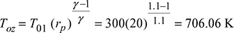
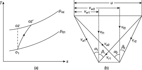 Figure 15.23 (a) T-s diagram, (b) Velocity diagrams
 Toz′ =766.7 Kvw2 = vf tan α2, vw1 = vf tan α1For Rd = 0.5, α2 = β1, α1 = β2Work consumed by compressor per kg of air= u (vw2 − vw1) ϕw × z= cp (Toz′ − T01)200 (tan α2 − tan α1) 160 × 0.88 × 18 = 1.005 (766.7 − 300)tan α2 − tan α1 = 9.25 × 10⁻⁴or tan β1 − tan α1 = 9.25 × 10⁻⁴
 Adding the above two equations, we get2 tan β1 = 1.250925or β1 = 32.02° = α2or tan α1 = 1.25 − 0.62546 = 0.62453α1 = 31.98° = β2
- Density of approaching air to first stage.
 Applying continuity equation,ρ1Afvf = ṁa1.1614 × π [1 − (0.8)2] × 160 = 300Tip radius, r1 = 1.194 mHub radius, rh = 0.8 r1 = 0.8 × 1.194 = 0.9558 mBlade height of first stage,h = r1 − rh = 1.194 − 0.9558 = 0.238 m.
Example 15.18
Air enters an axial flow compressor at 25°C and undergoes a pressure increase of six times that at inlet. The mean velocity of rotor blades is 200 m/s. The inlet and exit angles of both the moving and fixed blades are 45° and 20° respectively. The degree of reaction at the mean diameter is 50 percent and there are 10 stages in the compressor. The isentropic efficiency of compressor is 85% and axial velocity is constant throughout. Calculate the work done factor of the compressor.
Solution
Given: T1 = 273 + 25 = 298 K, rp = 6, um = 200 m/s, β1 = 45°, β2 = 20°, Rd = 50%, z = 10, (ηc)isen = 85%, vf 1 = vf 2 = vf
For Rd = 50%, α2 = β1 and α1 = β2
Also vr1 = va2 and vr2 = va1
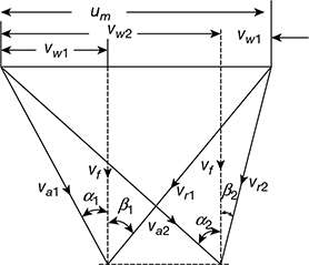
Figure 15.24 Velocity triangles
From Fig 15.24, we have
um = vr2 sin β2 + va2 sin α2
= va1 sin β2 + va1 cos α1 tan α2
200 = va1 [sin 20° + cos 20° tan 45°]
= 1.2817 va1
or va1 = 156 m/s
vw1 = va1 sin α1 = 156 sin 20° = 53.36 m/s
vw2 = va2 sin α2 = 207.3 sin 45° = 146.58 m/s
Δvw = vw2 − vw1 = 146.58 − 53.36 = 93.22 m/s
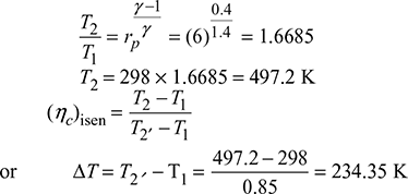
Work done on compressor, wc = cp × ∆T = 1.005 × 234.35 = 235.5 kJ/kg
Power input to compressor = ∆vw × um × ϕw × z
= 93.22 × 200 × ϕw × 10 = 186, 440 × ϕw
Work done factor, 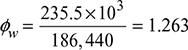
Example 15.19
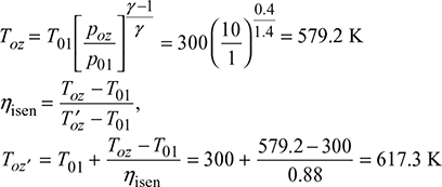
An axial flow compressor compresses the air up to overall stagnation pressure 10 bar with overall stagnation isentropic efficiency of 88%. The inlet stagnation pressure and temperature are 1 bar and 300 K. The mean blade speed is 200 m/s. The degree of reaction is 0.5 at the mean radius with air angles of 30° and 10° at rotor inlet and outlet with axial direction respectively. The work done factor is 0.88. The hub-tip ratio is 0.4. The mass flow rate is 50 kg/s. Show the compression process on T–s diagram and draw the inlet and outlet velocity triangles. Find (a) the stagnation polytropic efficiency, (b) the number of stages and (c) the blade height in first stage of the compressor.
Solution
Given: p1 = 1 bar, T01 = 300 K, poz = 10 bar, ηisen = 88%, um = 200 m/s, Rd = 0.5, β1 = 30°, β2 = 10°, ϕw = 0.88, ![]() , ṁ = 50 kg/s,
, ṁ = 50 kg/s,
The T–s diagram is shown in Fig. 15.25(a)
The velocity triangles are shown in Fig.15.25(b).
- Stagnation polytropic efficiency,
 = 0.9117 or 91.17%
 - For Rd = 0.5
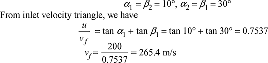
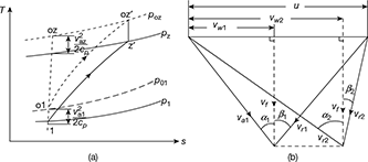 Figure 15.25 (a) T-s diagram, (b) Velocity trianglesvw2 = vf tan α2 = 265.4 tan 30° = 153.2 m/svw1 = vf tan α1 = 265.4 tan 10° = 46.8 m/sWork consumed per stage = ϕw u (vw2 − vw1)= 0.88 × 200 (153.2 − 46.8) × 10−3 = 18.726 kJ/kgTotal work consumed by compressor = cp (Toz′ − T01)= 1.005 (617.3 − 300) = 318.89 kJ/kg.Number of stages,
 Static temperature,
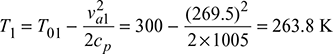
 ṁa = ρ1A1vf50 = 0.843 × π [1 − (0.4)2] × 265.4r1 = 0.291 m or 291 mmrh = 0.4 r1 = 0.4 × 291 = 116.4 mm
Example 15.20
An air compressor has eight stages of equal pressure ratio 1.35. The flow rate through the compressor and its overall efficiency are 50 kg/s and 82 per cent respectively. If the condition of air at entry are 1.0 bar and 40°C, determine:
- the state of air at the compressor exit,
- polytropic or small stage efficiency,
- efficiency of each stage,
- power required to drive the compressor assuming overall efficiency of the drive as 90%
Take cp = 1.005 kJ/kg K and γ = 1.4.
Solution
Given: z = 8, (rp)st = 1.35, ṁ = 50 kg/s, η0 = 82%, p1 = 1.0 bar, T1 = 313 K, ηmech = 90%, cp = 1.005 kJ/kg.K, γ = 1.4

 Exit pressure, pa = 1.0 × 11.03 = 11.03 bar
- Polytropic efficiency,
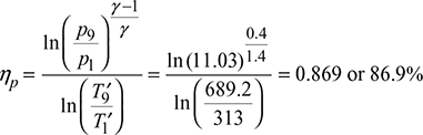
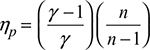
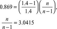 3.0415 n − 3.0415 = nor n = 1.49
 Isentropic efficiency of each stage
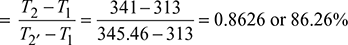
- Power required to drive the compressor,
Example 15.21
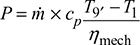
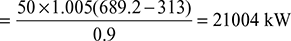
A small compressor has the following data:
Air flow rate = 1.5778 kg/s
Pressure ratio = 1.6
Efficiency = 85%
State of air at entry, p0p = 1.008 bar, T0p = 300 K
cp for air = 1.009 kJ/kg K.
- Calculate the power required to drive this compressor.
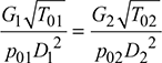
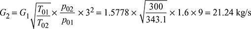
- A geometrically similar compressor of three times the size is constructed. Determine, for this compressor (i) mass flow rate, (ii) pressure ratio, (iii) speed, and (iv) the power required.
Assume same entry conditions and efficiency for the two compressors and also assume kinematic and dynamic similarities between the two machines.
Solution
Given: ṁa = 1.5778 kg/s, rp = 1.6, N = 54,000 rpm, η = 85%, p01 = 1.008 bar, T01 = 300 K, cp = 1.009 kJ/kg.K, D2 = 3D1
- Power required = ṁacp(T02′ − T01) = 1.5778 × 1.009 (350.725 − 300) = 80.75 kW
 = const., G = mass flow rate.
Example 15.22
Air at a temperature of 300 K enters a 10-stage axial flow compressor at the rate of 3.5 kg/s. The pressure ratio is 6.0 and the isentropic efficiency is 90%. The process is adiabatic and the compressor has symmetrical stages. The axial velocity of 120 m/s is uniform across the stages and the mean blade speed is 200 m/s. Assume that the temperature change is same in each stage.
Determine the direction of the air at entry to and exit from the rotor and stator blades. Also find the power given to the air.
For air, take cp = 1.005 kJ/kg.K and γ = 1.4.
Solution
Given: T1 = 300 K, z = 10, ṁa = 3.5 kg/s, rp = 6, ηisen = 90%, vf = 120 m/s, u = 200 m/s, cp = 1.005 kJ/kg.K, γ = 1.4
Symmetrical stages, same temperature change in each stage
The velocity diagrams are shown in Fig. 15.26
(ΔT)stage = (ΔT)overall/z
Increase in temperature per stage,
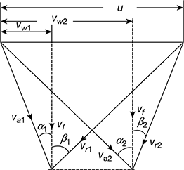
Figure 15.26 Velocity triangles
tan β1 = 1.2999, β1 = 52.43°, β2 = 20.14°
Power supplied = zṁacp(∆T)stage
= 10 × 3.5 × 1.005 × 22.284
= 783.84 kW
Example 15.23
An axial flow compressor of 50% reaction blading has isentropic efficiency of 82%. It draws air at 17°C and compresses in the pressure ratio of 4 : 1. The mean blade speed and flow velocity are constant throughout the compressor. The inlet and outlet angles of blades are 15° and 45° respectively (angles measured from axial direction). Blade speed = 180 m/s and work input factor = 0.84. Calculate (a) the flow velocity and (b) the number of stages. [IAS, 2002]
Solution
Given: Rd = 50%, ηisen = 82%, T1 = 17 + 273 = 290 K, rp = 4:1, um = const, vf = const., β1 = 15°, β2 = 45°, u = 180 m/s, ϕh = 0.84
For Rd = 50%, α1 = β2 = 45°, α2 = β1 = 15°
- From Fig. 15.27, we get
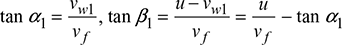
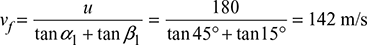 ∴ Flow velocity, vf = 142 m/swisen = cp (T2 − T1) = 1.005(430.9 − 290) = 141.6 kJ/kg
 Figure 15.27 Velocity triangles
- Work done per stage = u × ∆vw = 180 × 75.6 = 13.608 kJ/kgNumber of stages
Leave a Reply