The vapour compression refrigeration cycle with superheated vapour before compression on T-s and p-h diagrams are shown in Fig. 19.18. The evaporation starts at state 4 and continues upto state 1′, when it is dry and saturated. The vapours are now superheated from state 1′ to state 1, where they enter the compressor. Its effect is to increase the COP.
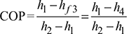
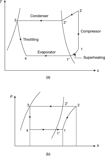
Figure 19.18 Superheated vapour compression cycle: (a) T-s diagram, (b) p-h diagram
1 Superheat Horn
Consider the T-s diagram for a vapour compression cycle shown in Fig 19.19. The vapours of refrigerant are wet at state 1′ and dry saturated at state 2′. The process 1′−2′ represents wet compression. The vapours at state 1 are dry saturated and at state 2 superheated. The process 1−2 represents dry compression. The increased work of the cycle due to the replacement of wet compression by dry compression appears as the area 2−2′−2′′, generally known as superheat horn.
Figure 19.19 Wet and dry compression processes
Leave a Reply