In the dual cycle, part of the heat is supplied at constant volume and the rest at constant pressure. This is also called mixed or limited pressure cycle. The p–v and T–s diagrams are shown in Fig. 9.10. The various processes are:
Process 1−2: Isentropic compression of air
Process 2−3: Constant volume heat addition
Process 3−4: Constant pressure heat addition
Process 4−5: Isentropic expansion of air
Process 5−1: Constant volume heat rejection
Considering 1 kg of working fluid,
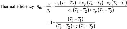
Heat supplied, qs = cv (T3 − T2) + cp (T4 − T3)
Heat rejected, qr = cv (T5 − T1)
Work done per cycle, w = qs – qr = cv (T3 – T2) + cp (T4 – T3) – cv (T5 – T1)
Let, ![]() = compression ratio
= compression ratio

Then from process 1−2, we have
T2 = T1rγ−1
From process 2 – 3, ![]()

Figure 9.10 Dual cycle: (a) p-v diagram, (b) T-s diagram
From process 4 – 5, 


The variation of thermal efficiency of dual cycle is shown in Fig. 9.11.
Mean effective pressure,

Now ![]()


Figure 9.11 Variation of thermal efficiency of dual cycle with compression ratio


Leave a Reply