This cycle is used for compression ignition internal combustion engines working on diesel oil. The p-v and T-s diagrams are shown in Fig. 9.8. It consists of four internally reversible processes two adiabatic, one constant pressure and one constant volume. The various processes are:
Process 1–2: Isentropic compression of air.
Process 2–3: Heat addition at constant pressure.
Process 3–4: Isentropic expansion of air.
Process 4−1: Heat rejection at constant volume.
Considering 1 kg of air.
Heat supplied, qs = q2–3 = cp (T3 – T2)
Heat rejected, qr = q4–1 = cv (T4 – T1)
Work done per cycle, w = qs – qr = cp (T3 – T2) – cv (T4 – T1)
Thermal efficiency,

Let ![]() = compression ratio
= compression ratio
Now 
Let ![]() = cut off ratio
= cut off ratio


Figure 9.8 Diesel cycle: (a) p-v diagram, (b) T-s diagram

The thermal efficiency of diesel cycle increases as compression ratio increases but decreases as cut-off ratio increases (Fig. 9.9). The thermal efficiency of diesel cycle is less than that of Otto cycle. The compression ratio for diesel cycle varies from 14 to l8.
Mean effective pressure ![]()

Now 


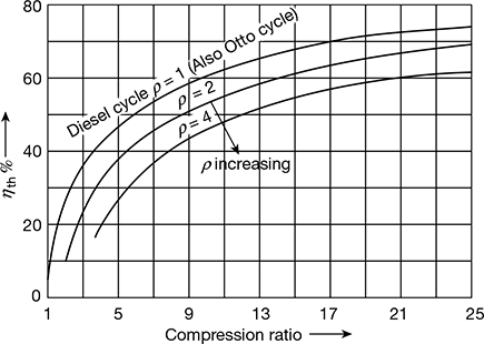
Figure 9.9 Diesel cycle thermal efficiency v’s compression ratio
Leave a Reply