The different methods commonly used for the measurement of dryness fraction of steam are as follows:
- Barrel Calorimeter
- Separating Calorimeter
- Throttling Calorimeter
- Combined Separating and Throttling Calorimeter.
The working principle of all the calorimeters is to bring the state of the substance from the two-phase region to the single phase region (either compressed liquid or superheated vapour region). This is because in the two-phase region, pressure and temperature are not independent variable, one is independent and the other is dependent. On the other hand, both in compressed liquid and superheated vapour region, both pressure and temperature are independent variables.
1 Barrel Calorimeter
The barrel calorimeter, shown in Fig. 2.10, consists of a copper barrel placed on wooden block and covered by a wooden cover. The barrel contains a known quantity of cold water and is surrounded by an outer vessel with air space in between, which acts as an insulator. The temperature is measured by a thermometer that passes through one of the holes in the wooden cover. The whole assembly is placed on the platform of a weighing bridge. The steam from the main steam pipe enters through the sampling tube via the control valve and flows into the cold water through fine exit holes of the ring provided at the end of the pipe. The condensation of steam takes place as it comes in contact with cold water, and as a result, the temperature of water rises. The quantity of steam condensed can be known from the difference of readings of the weighing bridge before and after the condensation of steam. The pressure of entering steam is indicated by the pressure gauge.

Figure 2.10 Barrel calorimeter
Let ms = mass of steam condensed
x = dryness fraction of steam
hfg = latent heat of steam
ts = temperature of formation of steam (corresponding to pressure indicated by the pressure gauge)
mw = mass of cold water in the calorimeter in the beginning
mc = water equivalent of calorimeter
t1 = initial temperature of cold water in the calorimeter
t2 = final temperature of the mixture after steam condensation
Heat lost by steam = ms[x × hfg + cps(ts − t2)]
Heat gained by cold water and calorimeter = (mw + mc) × cpw × (t2 − t1)
Heat lost by steam = Heat gained by cold water and calorimeter


This method gives only approximate results. The value of x calculated is always lower than the actual value as heat losses due to convection and radiation are not accounted for.
2 Separating Calorimeter
This calorimeter, shown in Fig. 2.11, consists of two concentric chambers that communicate with each other through an opening at the top. The steam to be tested flows from the main steam pipe through a sampling tube to the calorimeter pipe through the valve which must be fully open when testing. The metal basket has a large number of perforations through which the steam discharges. The water particles due to their heavier momentum get separated from the steam and get collected in the inner chamber. The quantity of water collected is indicated by the level in the gauge glass and the pointer that moves on a scale. The dry steam in the inner chamber moves up and then down again through the annular space between the two chambers. The gauge fitted has two scales: the inner one indicates the pressure, whereas the outer one indicates the rate of discharge of dry saturated steam during a predefined time interval. Then the steam then flows through the calibrated orifice to the bucket calorimeter which is placed on the platform balance by which the most of steam discharged can be further confirmed.
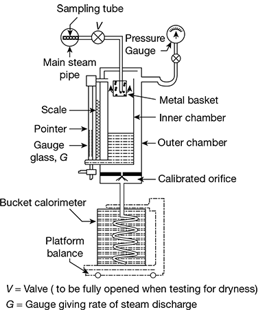
Figure 2.11 Separating calorimeter
Let ms = mass of dry steam condensed
mw = mass of suspended moisture collected

It is not possible to remove all the water particles from steam, and the dryness fraction calculated by this method is always greater than the actual. However, it is a quick method and is used for the measurement of dryness fraction for very wet steam.
3 Throttling Calorimeter
The throttling calorimeter, shown in Fig. 2.12, consists of the sampling tube through which the steam from the main steam pipe flows through the throttling valve and becomes superheated. The steam then flows into the inner chamber, flows down, and rises up again to enter the annular space. The loss of heat by radiation from the inner chamber is minimised by the hot steam around the outside of the inner chamber. The temperature of throttled steam is measured by the thermometer placed in the pocket filled with cylinder oil. To obtain good results, the steam issuing from the throttle valve must be superheated. To ensure this, a manometer is attached to measure the pressure of steam. Corresponding to this pressure, the saturation temperature of steam must be lower than the temperature indicated by the thermometer. The steam finally escapes through the exhaust. This calorimeter is suitable for steam having high dryness fraction.
Let p1 = initial pressure of wet steam before expansion
x1 = dryness fraction of wet steam
hfg1 = latent heat of vapourization of wet steam
tsup = temperature of superheated steam after expansion
hfg2 = latent heat of vapourization of steam after expansion
ts2 = saturation temperature of steam after expansion
cps = specific heat of superheated steam at constant pressure
Enthalpy of steam before throttling = hf 1 + x1 hfg1

Figure 2.12 Throttling calorimeter
Enthalpy of steam after throttling = hf 2 + hfg2 + cps (tsup − ts2)
Enthalpy before throttling = Enthalpy after throttling
hf 1 + x1 hfg1 = hf 2 + hfg2 + cps (tsup − ts2)

4 Combined Separating and Throttling Calorimeter
The combined separating and throttling calorimeter is shown in Fig. 2.13. The steam is first passed through the separating calorimeter where it losses most of its moisture and becomes comparatively drier. It is then passed through the throttling calorimeter where superheating takes place without change of enthalpy. The temperature and pressure of steam after throttling are measured by using a thermometer and pressure gauge, respectively.
Let p1 = pressure of wet steam entering the throttling calorimeter
x1 = dryness fraction of steam
hfg1 = latent heat of entering steam
mw = mass of suspended moisture collected
ms = mass of steam leaving the separating calorimeter and entering the throttling calorimeter
p2 = pressure of steam after throttling
hfg2 = latent heat of steam at pressure p2
Enthalpy of steam entering throttling calorimeter = Enthalpy of steam leaving throttling calorimeter
hf 1 + x1hfg1 = (hf 2 + hfg2) + cps (tsup − ts2)
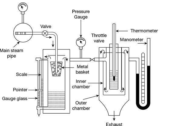
Figure 2.13 Combined separating and throttling calorimeter


and x = dryness fraction of steam entering the separating calorimeter
Mass of dry steam entering the whole apparatus = ms x1


This calorimeter gives quite satisfactory results when the steam is considerably wet.
Leave a Reply