The basic function of the hydraulic cylinder is to convert fluid power into linear machine lift force at that time the cylinder is subjected to internal pressure of the fluid or oil. Since the internal pressure should be high enough to sustain the load then the cylinder must be a heavy-duty cylinder which is expected to be thick to sustain the pressure.
Material selection
Both cast and drawn materials can be selected as cylinder materials for variable height vehicle but the most frequently selected material is called cold drown deep polished low carbon steel with relatively high stress value.
But due to the following reasons we have selected the stainless steel with mechanical properties given below as cylinder material
- Manufacturing feasibility
- Local availability
| Material selected | stainless steel |
| Grade | AISI302 |
| Ultimate tensile stress | σu=655Mpa |
| Yield tensile stress | σy=260Mpa |
| Allowable shear stress | τall=150Mpa |
| Modules of elasticity | E=200Gpa |
| Modules of rigidity | G=77Gpa |
Design snalysis
The wall develops both tangential and radial stress with valves which depend upon the radius.
- Assuming that the longitudinal fibber of the cylinder is equivalently strained
- We can analyze the design as follows
Now the pressure and the thickness can be analyzed using Lame’s equation as follows.
The cylinder is subjected to both radial and tangential stress σr and σt.
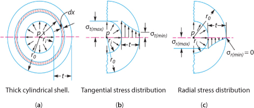
- tangential stress at any radius x
Where, pi = inner pressure
ri=inner radius
ro=outer radius
- radial stress at any radius x is given as:
Since there is no external pressure pO = 0. Then,
σt is maximum at x=ri and the minimum at x=ro
 is maximum at x = ri and 0 at x = ro
- Now we can use the maximum strain energy theory to evaluate the cylinder failure, Where Bernie equation is derived to calculate the cylinder thickness.
- ro = ri + t and the maximum strain theory we get the following equation called Bernie’s equation
 Where µ = poison’s ratio
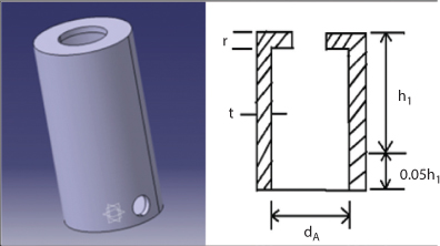
- From geometric analysis the internal diameter of the main cylinder was found to be d1 = 14cm for diameter of the piston rod (dp=8cm), but during piston design dp was corrected to 7cm
Thus the modified main cylinder is;
d1 = 7+2(head thickness of piston) +2(clearance between piston head and the cylinder)
d1 = 7+2+2c
= 7+2(1.5) +2(1)
= 10cm - Let us take factor of safety n=2.3
Then
- Oil pressure in cylinder tube can be found as:
Balancing force vertically

Assuming the piston is moving upward with uniform velocity the acceleration a=0

Where, d1– ismain cylinder diameter.
- This pressure is the same over the walls of the tube
- The thickness of the main cylinder is
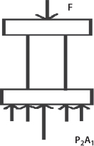 Figure 4.14 Force acting on piston.µ=Poisson’s ratio can be found as follows:Elasticity and rigidity modulus are related by the following equation :
 Then the thickness t is,
 The thickness of the main cylinder can be taken as t = 9mm
Leave a Reply