| Ground clearance | 20 cm |
| Kerb weight | 1270 kg |
| Gross weight | 1900 kg |
| Overall height | 1450 mm |
| Overall length | 4505 mm |
| Overall width | 1755 mm |
| Tires | 195/65/R15 |

Dimension and Force Analysis of the Pedal
Hydraulic system uses positive displacement input and output device require force analysis. Variation in length and points of supports on this vehicle pedal gives various outputs; thus iteration for acceptable range of length will be important.
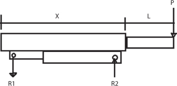
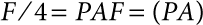
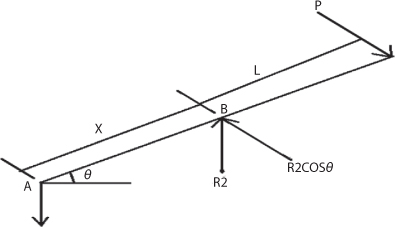
Case 1: when the pump piston or plunger is at its lowest position
Where piston is the force that the driver applies on the pedal.
R1- reaction force b/n the link and pedal
R2- reaction force b/n the plunger and the pedal
The pedal socket can be at equilibrium when the force and the momentum should be balanced.
(4.1)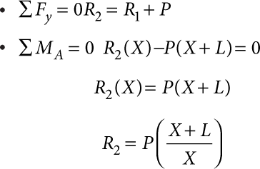
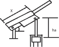
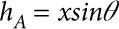
Case 2: when the plunger is at its maximum position
- this happens when the operator up strokes or moves the pedal rise up; this can be shown diagrammatically as follows
- this is the maximum height of the plunger and socket
Where hA – the distance through which the piston in the pump moves.
θ – The maximum angle through which the pedal moves with horizontals.
Now, 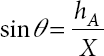
(4.2)![]()
Considering Pascal’s low of the fluid or oil in the cylinder of the vehicle
- When valve 1 is closed then the oil’s route or path is actuating the cylinders
- Valve 2 actuating pipe
- Main cylinder
- Fr this route or path the pressure is constant all over the path(if valve 1 is closed)
- Assuming that the typical oil or fluid is incompressible we can apply Pascal’s law to the system (the pistons and the path of the oil above)
If F is the load acting on the piston and R2 be the force acting on the plunger actuator (piston) then
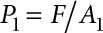
Where p- is the pressure require in the fluid require to hold the piston in equilibrium and
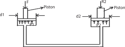
A- The area of the main cylinder
The force necessary to keep the actuator piston in equilibrium will be
R2 = P2A2 Where A2 area of the actuator cylinder
From Pascal’s law P2 = P1 thus from the piston
And from the actuating cylinder P2 = R2 / A2
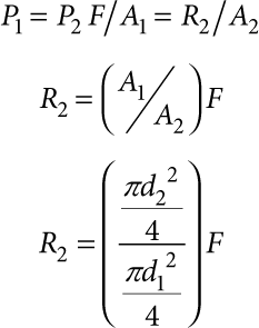
(4.3)
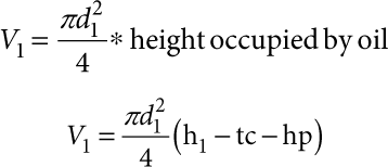
- Considering volume relation of the cylinders
- In order to bring the piston to its maximum possible position the actuator cylinder must be moved’ times up and down n is in other words called the number of stroke needs to which the maximum lift height volume of cylinder filled to move the piston
= n (volume of cylinder moved by the actuating piston)

Where, V1 – volume of main cylinder
V2 – volume of the actuating cylinder when the plunger up to its maximum position
(4.4)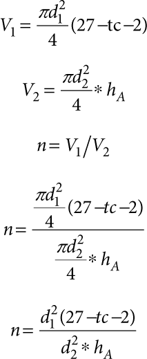
Now we have got four equations containing the unknown parameter of the geometry.
Now we can summarize the equation as follows,
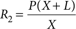
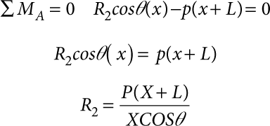
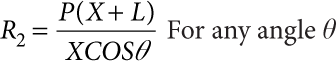
But this holds true when the pedal is a horizontal position; when the pedal is deflected by an angle θ then the reaction force R2 is given by
R2 – Is actuating vertical reaction
P – Is always perpendicular to the pedal axis
- Now taking summation of moment due to all force at A will be zero
 When the pedal is at the horizontal position then then the reaction force becomes then θ = 0 then the reaction force becomes
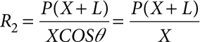 Which is the same with equation (1) derived earlier
 - Thus, the reaction force R2 can more generally be written as
 Let us summarize the equations,(1)
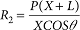 (2)
(2) (3)
(3) (4)
(4)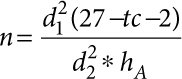 D1=dP + 2(lower thickness of piston) + 2(clearance b/n the piston head and cylinder)
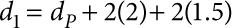 Where, d1 – internal diameter of main cylinder
 Figure 4.10 Connection of piston and cylinder.
- Let the range of the force the driver can apply on the pedal vary from 200–400N
- Length of the pedal and socket
- Let the length of the pedal L be vary from 400–600mm
- Let the length of the socket b/n the hole of the pin joint X vary from 30–40mm
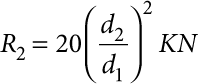
- Now the driver wants to apply a force of 260N on the pedal the iteration will produce as follow with an objective of finding the possible number of strokes to practically raise the piston up to the indicated maximum lift height
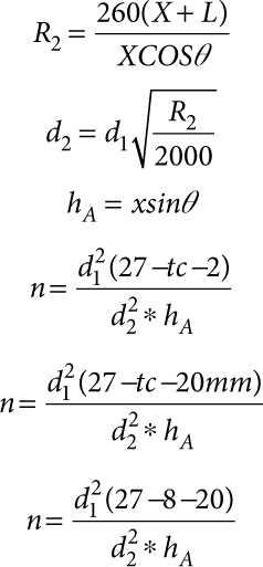
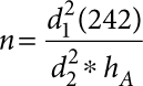
As can be seen from Table 4.3, we made five iterations to calculate the unknown over the indicated range of the assumed value, although many designers select a different iterative approach objective. We have selected the optimum and frequently observed number of strokes to be our objective of the iteration process looks the two extremes of the iteration, that is, iteration number 1 and number 2. The first one is too much to be used for 20 KN load and it is mostly stroke number for loads high in magnitude and number 5 is too small to raise the load, thus the 2nd iteration contains the most practicable number of stocks, that is n = 22.2. Then the processing design analysis of each part will depend on the value of parameters obtained from the 3rd iteration.
Table 4.3 Iteration.
| Known | Assumption | Calculated value | |||||||||
| No iter | H min | H max | P | L | X | d1 | θ | d2 = d1√R2/20 | hA = xsinθ | R2 = (X+L) p/XCOSθ | n = d12*242/d22*hA |
| 1 | 270 | 470 | 260 | 400 | 30 | 100 | 30 | 58.6 | 13.6 | 4.3 | 30 |
| 2 | 270 | 470 | 260 | 450 | 30 | 100 | 35 | 60 | 15.67 | 4.87 | 22.2 |
| 3 | 270 | 470 | 260 | 480 | 30 | 100 | 40 | 62.5 | 17.63 | 5.46 | 17.07 |
| 4 | 270 | 470 | 260 | 500 | 30 | 100 | 45 | 70.6 | 19.48 | 6.04 | 13.65 |
| 5 | 270 | 470 | 260 | 550 | 30 | 100 | 50 | 75.4 | 21.2 | 7.1 | 10.6 |
Generally, the geometry analysis of this system can be summarized,
| Height of the main cylinder | 27cm |
| Height that the vehicle rises | 20cm |
| The applied force | 260N |
| Diameter of main cylinder | 10cm |
| Angle that the pedal makes with horizontal | 35° |
| Diameter of actuator cylinder | 60mm |
| Maximum rise of the plunger | 15.67mm |
| Vertical plunger pin reaction force | 4.87KN |
| Number of stroke | 22.2 ≈ 23 |
Total Height of the piston = head of the piston + height of piston
= 2+20 =22cm
Leave a Reply