In order to balance the demand and supply of air, it is necessary to incorporate devices for the compressor control. The common methods of control are as follows:
- Throttle control: When the demand is less, there is build-up of pressure in the receiver, and the high pressure air from the receiver is led to piston and cylinder. The movement of piston is resisted by a spring. However, with excessive pressure, the piston depresses the spring, thus closing partly the suction valve. Therefore, during the suction stroke, the air intake is partly throttled. The reverse action takes place when the pressure in the receiver drops due to increase in demand.
- Clearance control: In this method, clearance pockets are provided for increasing or decreasing clearance. Therefore, the volumetric efficiency is reduced in proper proportion to control output.
- Blowing air to waste: In case of excessive pressure built-up in the receiver due to decrease in demand, a by-pass valve from the high pressure cylinder delivers air directly to atmosphere. When the pressure in the receiver drops, the relay piston closes the valve.
Example 12.1
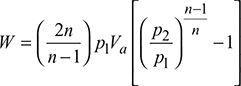
A single-stage reciprocating air compressor is required to compress 72 m3 of air per minute from 15°C and 1.0 bar to 8 bar pressure. Find the temperature at the end of compression, work done, power, and heat rejected during each of the following processes: (a) isothermal, (b) adiabatic, and (c) polytropic compression following the law pV1.25 = constant.
Solution
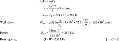
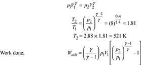
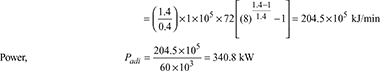
Note: Example 9.1 illustrates that isothermal compression requires the minimum compression work, while isentropic compression requires the maximum for the same suction and delivery pressure.
Example 12.2
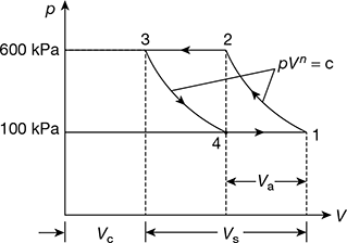
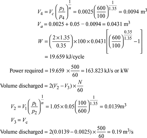
A double-acting reciprocating compressor with a piston displacement of 0.05 m3 per stroke operates at 500 rpm. The clearance is 5 per cent and it receives air at 100 kPa, discharges it at 600 kPa. The compression is polytropic, pV1.35 = c. Determine the power required and the air discharged in m3/s.
Solution
The p–V diagram for the compressor is shown in Fig. 12.19.
Va = Vc + Vs − V4
Vc = 0.05 × 0.05 = 0.0025 m3
Example 12.3
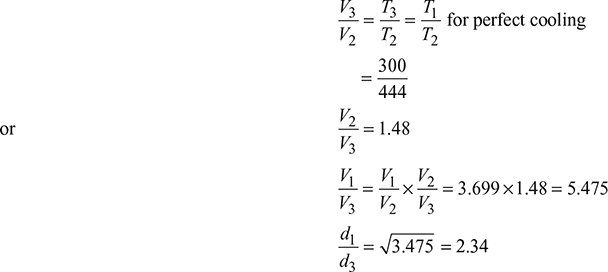
A double-acting reciprocating compressor with complete intercooling delivers air to the main at a pressure of 30 atm, the suction condition being 1 atm and 27°C. If both cylinders have the same stroke, then find the ratio of the diameters of the cylinders for the efficiency of compression to be a maximum. Assume the index of compression to be 1.3.
Solution
Volume of L.P. cylinder = V1
Volume of H.P. cylinder = V3
L1 = L3
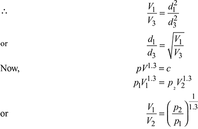
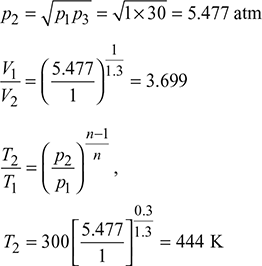
From constant pressure process 2–3: (see Fig. 12.12)
Example 12.4
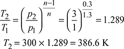
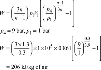
A double-acting reciprocating compressor with perfect intercooling takes in air at 1 bar and 27°C. The law of compression in both the stages is pV1.3 = constant. The compressed air is delivered at 9 bar from the H.P. cylinder to an air receiver. Calculate per kg of air (a) the minimum work done, (b) the heat rejected to the intercooler, and (c) the minimum work done in a three-stage compressor working under the same conditions. Take cp = 1.005 kJ/kg.K.
Solution
T1 = 273 + 27 = 300 k
For 1 kg of air, p1v1 = RT1,
or v1 ![]() = 0.861 m3/kg
= 0.861 m3/kg
- The minimum work required in two-stage compressor with perfect intercooling is,
 The intermediate pressure is found to be
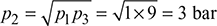
 Heat rejected to intercooler,q = cp (T2 − T3) = cp (T2 − T1) [∴T2 = T3]= 1.005(386.6 − 300) = 87 kJ/kg of air
- The least work done in case of three-stage air compressor working between the same pressure limits is given by,
Example 12.5
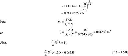
A single-stage, single-acting reciprocating compressor delivers 15 m3/min of free air from 1 bar to 8 bar at 300 rpm. The clearance volume is 6% of the stroke volume, and compression and expansion follow the law pV1.3 = constant. Calculate the diameter and stroke of the compressor. Take L = 1.5 D. The temperature and pressure of air at suction are the same as atmospheric air.
Solution
Clearance ratio, c = 0.06
Volumetric efficiency, 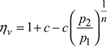
D = 0.3817 m or 38.17 mm
L = 1.5 × 0.3817 = 0.5726 m or 57.26 mm
Example 12.6
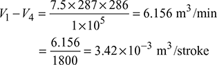
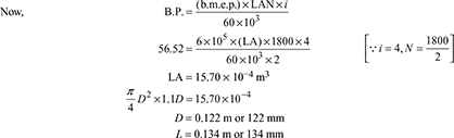
A two-cylinder, single-acting reciprocating air compressor is to deliver 15 kg of air per minute at 6.5 bar from suction conditions 1 bar and 13°C. Clearance may be taken as 4 per cent of stroke volume and the index for both compression and re-expansion as 1.3. The compressor is directly coupled to a four-cylinder, four-stroke petrol engine that runs at 1800 rpm with b.m.e.p. of 6 bar. Assuming a stroke–bore ratio of 1.1 for both engine and compressor and a mechanical efficiency of 85% for the compressor, calculate the required cylinder dimensions. Take R = 287 J/kgK.
Solution
The p−V diagram for the compressor is shown in Fig. 12.20.
Amount of air delivered per cylinder ![]()
Now, p1(V1 − V4) = mRT1
From the expansion curve, we have
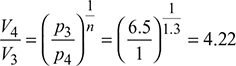
V4 = 0.1688 Vs
Now, V1 = V3 + Vs = 0.04 Vs + Vs = 1.04 Vs
V1 − V4 = (1.04 − 0.1688) Vs = 0.8712 Vs = 3.42 × 10⁻³
Vs = 3.9256 × 10⁻³ m3
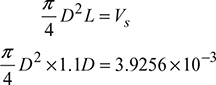
D = 0.1656 m or 165.6 mm
L = 1.1 D = 0.1822 m or 182.2 mm
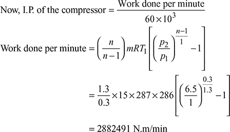
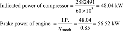
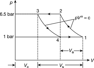
Figure 12.20 p-V diagram
Example 12.7
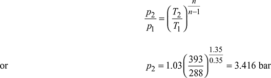
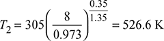
A multistage reciprocating compressor has to be designed to supply air at 135 bar, while atmospheric condition is 1.03 bar and 15°C. The value of compression index may be assumed as 1.35. Due to practical reasons, the intercoolers are not able to cool the air below 45°C, while the maximum temperature allowable in the system is 120°C. Calculate the number of stages that are necessary in the compression and the rate of cooling water circulated per kg of air. Take cp = 1 kJ/kg. K.
Solution
The p−V diagram for the compressor is shown in Fig. 12.21.
T1 = 273 +15 = 288 K, p1 = 1.03 bar, n =1.35
Since the maximum allowable temperature is 120°C, the temperature after first stage of compression,
T2 = 273 + 120 = 393 K
The intercoolers cool the air from T2 = 393 K to T3 = 273 + 45 =318 K. For the second stage, the inlet temperature is T3 = 318 K and outlet temperature is T4 = 393 K (see Fig. 12.10b).
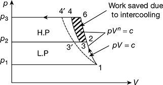
Figure 12.21 p-V diagram
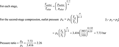
The pressure ratio is same for all the subsequent stage till the pressure reaches 135 bar. Hence, the number of stage i can be calculated from,
i ln 2.26 = ln 3.952
i = 4.51
Therefore, the minimum number of stages required including the first stage
= 4.51 + 1 = 5.51 ~ 6
Heat received by stage coolers per kg of air compressed
= cp (T2 − T3) (i − 1) = 1(393 − 318) × 5 = 375 kJ
Cooling water circulated per kg of air ![]()
Example 12.8
A single-acting, two-stage reciprocating compressor with complete intercooling delivers 10 kg/min of air at 16 bar. The suction occurs at 1 bar and 27°C. The compression and expansion processes are reversible with polytropic index n = 1.3. The compressor runs at 450 rpm. Calculate the following:
- The power required to drive the compressor.
- The isothermal efficiency.
- The free air delivered.
- The heat transferred in intercooler.
- The swept and clearance volumes for each cylinder if the clearance ratios for L.P. and H.P. cylinders are 0.04 and 0.06, respectively.
Solution
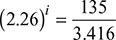
The p − V diagram is shown in Fig. 12.22.
p1 = bar, p3 = 16 bar, T1 = 273 + 27 = 300 K, N = 450 rpm, n = 1.3, c1 = 0.04, and c2 = 0.06
For perfect intercooling, ![]()
Figure 12.22 p − V diagram for two-stage compressor
- Work done in two stages with perfect intercooling,
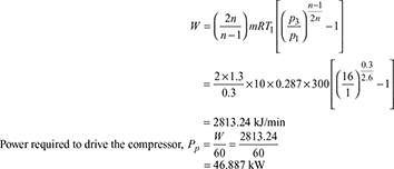
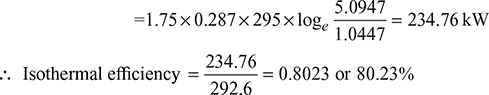
- Isothermal power,
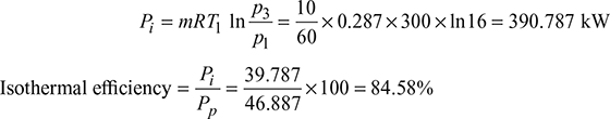
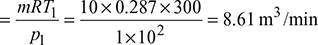
- Free air delivered
 Heat transferred in intercooler with perfect intercooling
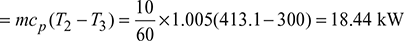
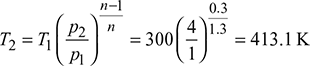
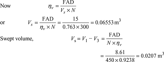 Clearance volume = c1 (V1 − V3) = c1Vs = 0.04 × 0.0207= 8.285 × 10⁻⁴ m3
- H.P. stage:
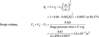 Clearance volume = c2Vs = 0.06 × 5.4 × 10−3 = 3.24 × 10⁻⁴ m3
Example 12.9
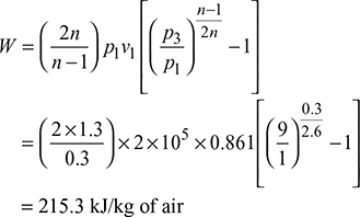
A reciprocating compressor is to be designed to deliver 4.5 kg/min of air from 100 kPa and 27°C to compress through an overall pressure ratio of 9. The law of compression is pV1.3 = constant. Calculate the saving in power consumption and gain in isothermal efficiency, when a two-stage compressor with complete intercooling is used in place of a single-stage compressor. Assume equal pressure ratio in both the stages of the two-stage compressor. Take R = 0.287 kJ/kg K.
Solution
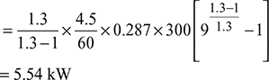
Given: m = 4.5 kg/min, p1 = 100 kPa, T1 = 273 + 27 = 300 K, rp = 9, n = 1.3
Rate of work required in single-stage compression 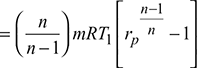
Rate of work required in two-stage compression 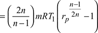
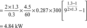
Saving in power = 5.54 − 4.84 = 0.70 kW
Example 12.10
A double-acting, single-cylinder reciprocating air compressor has a piston displacement of 0.015 m3 per revolution, operates at 500 rpm, and has 5% clearance ratio. The air is received at 1 bar and delivered at 6 bar. The compression and expansion are polytropic with n = 1.3. If the inlet temperature of air is 20°C, determine (a) the volumetric efficiency, (b) the power required and (c) the heat transferred and its direction, during compression.
Solution
Given that Vs = 0.015 m3/rev, N = 500 rpm, c = Vc/Vs = 0.05
p1 = 1 bar, p2 = 6 bar, n = 1.3, T1 = 273 + 20 = 293 K
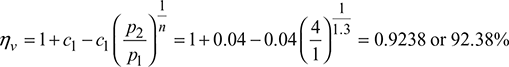
- Volumetric efficiency,

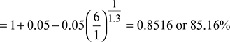
- Volumetric efficiency
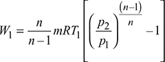
 or Va = 0.015 × 0.8516 × 500 × 2 = 12.774 m3/minPower required,
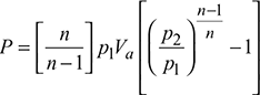
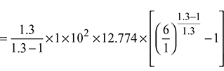 = 2834.54 kJ/min or 47.242 kW
 - Mass of air sucked,
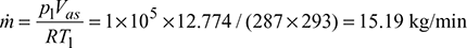
 Heat transferred during compression,
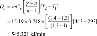
Example 12.11
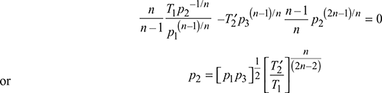
Find the optimum intermediate pressure of a two-stage reciprocating compressor, if intercooling is done up to a temperature ![]() , which is greater than the inlet temperature.
, which is greater than the inlet temperature.
Solution
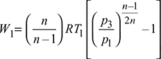
Work done in the L.P. cylinder (Fig. 12.23)
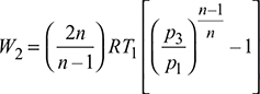
Work done in the H.P. cylinder,
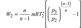
Total work done, W = W1 + W2
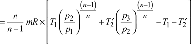
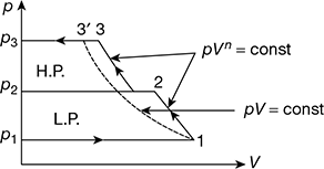
Figure 12.23 p − V diagram for two-stage compressor
Example 12.12
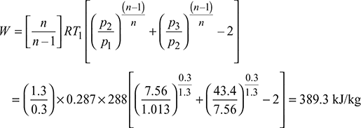
A two-stage reciprocating air compressor takes in air at 1.013 bar and 15°C and delivers at 43.4 bar. The intercooler pressure is 7.56 bar. The intercooling is perfect and the index of compression is 1.3. Calculate the work done in compressing 1 kg of air. If both cylinders have the same stroke and the piston diameters are 9 cm and 3 cm and the volumetric efficiency of the compressor is 90%, will the intercooler pressure be steady or will rise or fall as the compressor continues working?
Solution
Given that p1 = 1.013 bar, T1 = 273 + 15 = 288 K
p3 = 43.4 bar, p2 = 7.56 bar, n = 1.3,
m = 1 kg, d1 = 9cm, d2 = 3 cm, ηv = 0.9
Input work per kg for perfect intercooling T3 = T1,
Compression in L.P. cylinder:
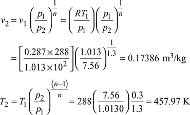
For constant pressure in the intercooler, the volume of air leaving the intercooler and entering the H.P. cylinder,
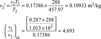
Ratio of effective cylinder volumes,
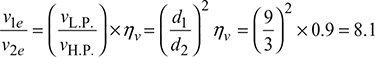
As 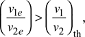 more air is supplied to H.P. cylinder than it can hold and consequently the pressure in the intercooler will rise.
Example 12.13
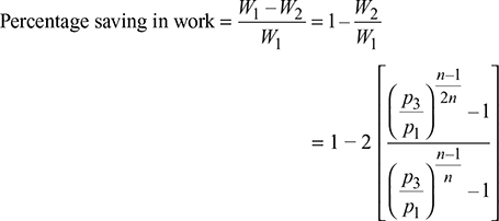
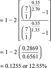
Find the percentage saving in work done by compressing air in two stages from 1 bar to 7 bar instead of one stage. Assume compression index 1.35 in both the cases and optimum pressure and complete intercooling in two-stage compression.
Solution
Given that p1 = 1 bar, p3 = 7 bar, n1 = n2 = 1.35
For perfect intercooling, ![]() = 2.646 bar and T3 = T1
= 2.646 bar and T3 = T1
With compression in one stage (see Fig. 12.7) without clearance, work done per kg of air is given by,
Work done with perfect intercooling,
Example 12.14
A single-stage, double-acting reciprocating air compressor delivers 3 m3 of free air/min at 1.013 bar and 20°C to 8 bar with the following data:
Rotational speed = 300 rpm, mechanical efficiency ηmech = 0.9, pressure loss in passing through intake valve = 0.04 bar, temperature rise of air during suction stroke = 12°C, clearance volume = 5% of stroke volume. Index of compression and expression = 1.35, and length of stroke = 1.2 times of the cylinder diameter. Calculate: (a) volumetric efficiency, (b) cylinder dimension, (c) indicated power, and (d) isothermal efficiency of the compressor, take for air, R = 0.287 kJ/kg K.
Solution
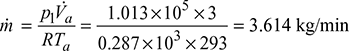
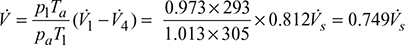
Given that Va = 3 m3/min, pa = 1.013 bar, Ta = 273 + 20 = 293 K, p1 = 1.013 − 0.04 = 0.973 bar, T1 = Ta + 12 = 293 + 12 = 305 K, Vc = 0.05Vs, n = 1.35, L = 1.2D, R = 0.287 kJ/kg K, N = 300 rpm
The p − V diagram is shown in Fig 12.24.
Mass of free air delivered,
Compression process 1–2:
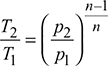
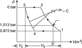
Figure 12.24 p − V diagram for single stage compressor
V̇3 = V̇c = 0.05V̇s
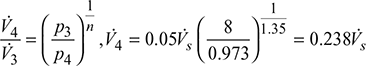
V̇1 − V̇4 = (V̇c + V̇3) − V̇4 = (0.05V̇s + V̇s) − 0.238V̇s = 0.812V̇s
Corresponding value of F.A.D. per cycle,
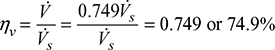
- Volumetric efficiency,
- Volume of air inhaled per cycle,
 Stroke volume, Vs =
  = 0.94248D3 m3/cycleAlso stroke volume =
  = 6.6756 ×10⁻³ m3/cycle∴ 0.94248D3 = 6.6756 × 10⁻³D = 0.192 m or 192 mmL = 1.2 × 192 = 230.4 mm
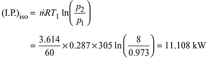
 - Indicated power, I.P. =
 ṁR (T2 − T1)
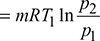
- Isothermal indicated power,
 Isothermal efficiency,
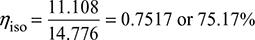
Example 12.15
The following data were obtained from a performance test of a 14 cm × 10 cm single stage reciprocating air compressor having 3 percent clearance: barometer 77 cm Hg, suction pressure 0 bar gauge, suction temperature 22°C, discharge pressure 4.05 bar gauge, discharge temperature 174°C, shaft rpm 1160, shaft power 350 kW, mass of air delivered per minute 1.75 kg. Determine (a) the actual volumetric efficiency; (b) the approximate indicated power; (c) the isothermal compression efficiency; (d) the mechanical efficiency and (e) the overall efficiency of the unit. Take patm = 1.031 bar.
Solution
Atmospheric pressure corresponding to 77 cm Hg
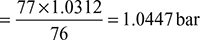
∴ p1 = 0 + 1.0447 = 1.0447 bar
and p2 = 4.05 + 1.0447465 = 5.0947 bar
Air entering the cylinder ![]()
Piston displacement 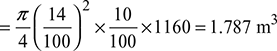
- Volumetric efficiency
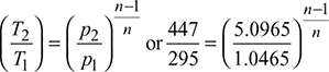 ∴ Compression index n = 1.353
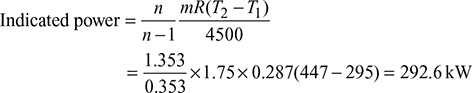
- Isothermal power
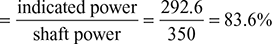
- Compressor mechanical efficiency
- Overall efficiency = isothermal efficiency × mechanical efficiency= 0.8023 × 0.836 = 67.07%
Example 12.16
A two-stage reciprocating compressor is used to compress from 1.0 bar to 16 bar. The compression is as per the law pV1.25 = const. The temperature of air at inlet of compressor is 300 K. Neglecting the clearance and assuming perfect intercooling find out the minimum indicated power to deliver 5 m3/min air measured at inlet conditions and find the intermediate pressure also.
Solution
Given: p1 = 1 bar v1 = 5m3/min = 0.083 m3/s, p3 = 16 bar, n = 1.25, T1 = 300 K
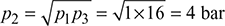
For complete intercooling, the intercooler pressure,
Work done in compressing the air,
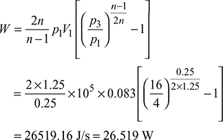
Power required to drive the compressor is 26.519 kW.
Leave a Reply