The cross-section of a typical axial flow compressor is shown in Fig. 15.1. It consists of adjacent rows of moving and fixed blades. The moving blades are mounted on the rotating drum and the fixed blades are fixed to the casing or stator. One stage of the compressor comprises a row of moving blades, followed by a row of fixed blades.
The blades belong to the aerofoil section designed on the basis of aerodynamic theory. Such a design prevents losses due to shock and turbulence and is free from stalling problems. The blades are said to be stalled when the air stream fails to follow the blade profile.
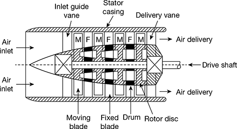
Figure 15.1 Typical axial flow compressor
The blades of a reaction gas turbine have profile formed by a number of circular arcs. This occurs because the acceleration process carried out in the converging blade passages of a reaction turbine is much more efficient and stable as against the diffusing or decelerating process carried out in the diverging passage between the blades of an axial flow compressor.
To keep the flow velocity constant throughout the compressor length, the annular area is reduced from inlet to outlet of the compressor. In the diverging passage of the moving blades, there is a rise in temperature due to diffusion and the absolute velocity is also increased due to work input.
The fixed blades serve to convert a part of the kinetic energy of air into pressure energy by diffusion and also guide and redirect the air stream to enter the next stage without shock.
Leave a Reply