The elements of steam power plants are as follows:
- Boiler
- Steam turbine
- Condenser
- Feed pump
The schematic diagram of a steam power plant is shown in Fig. 4.1. The p-v and T-s diagrams for the Carnot vapour power cycle are shown in Fig. 4.2(a) and (b). Dry and saturated steam at temperature TH = T1 enters the steam turbine and is expanded isentropically to sink temperature TL = T2 to do work. The exhaust steam from the turbine is condensed and cooled in the condenser to state 3 at which the working fluid is in a two-phase mixture of water and its vapour. The water and the vapour are then pumped by the boiler feed pump to state 4 in a saturated state to the boiler, where it is converted into steam.
Consider 1 kg of the working fluid for analysis.
Work done by steam turbine wt = w1 − 2 = h1 − h2
Work done on the pump, wp = w3 − 4 = hf4 − h3
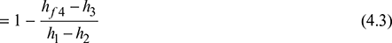
Net work, wnet = w1 − wp = (h1 − h2) − (hf4 − h3)
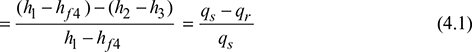
= (h1 − hf4) − (h2 − h3) = qs − qr
Heat supplied, qs = h1 − hf4
and heat rejected, qr = h2 − h3
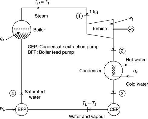
Figure 4.1 Schematic diagram of steam power plant
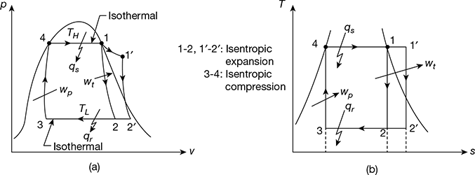
Figure 4.2 p-v and T-s diagrams for Carnot vapour cycle: (a) p-v diagram,(b) T-s diagram
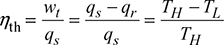
Thermal efficiency, ![]()
From the second law of thermodynamics, we have
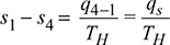
Similarly, ![]()
or qr = TL (s2 − s3)
Since, s1− s4 = s2 − s3, one can write

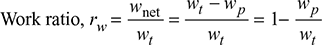
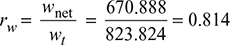
- Work Ratio (rw): It is defined as the ratio of net work done to turbine work done in the cycle.
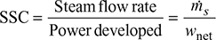
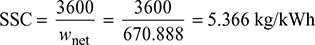
- Specific Steam Consumption (SSC): It is defined as the flow rate of steam per unit of power developed. It is expressed in kg/kWh.
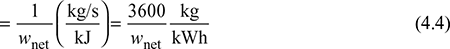
- Heat Rate: It is defined as the rate of heat supplied to produce unit work output.

1 Drawbacks of Carnot Cycle
The major drawbacks of Carnot cycle are as follows:
- It is very difficult to build a pump which can pump isentropically a two-phase mixture of water and its vapour at state point 3 and to deliver saturated water at state point 4.
- It is very difficult to superheat steam at constant temperature along path 1–1′.
- The steam leaving the turbine is of very low dryness fraction. It causes erosion and pitting on turbine blades.
- The volume of water vapours to be handled by the pump is quite large. It requires a very largesized pump, thus resulting in high power consumption.
- It requires high specific steam consumption, giving low thermal efficiency. Hence, it is not economically viable.
Example 4.1
A steam power plant operates on an ideal Carnot cycle. Dry saturated steam at 20 bar pressure is supplied to a turbine. It expands isentropically to a condenser pressure of 0.075 bar. Assuming that saturated water enters the boiler, calculate (a) the thermal efficiency, (b) the work ratio, and (c) the specific steam consumption.
Solution
For dry saturated steam at 20 bar, from the steam tables, we have
h1 = hg = 2799.5 kJ/kg, s1 = sg = 6.3408 kJ/kg.K
At 0.075 bar condenser pressure, from the steam tables, we have
hf2 = 168.77 kJ/kg, hfg2 = 2406.0 kJ/kg,
sf2 = 0.5763 kJ/kg.K, sfg2 = 7.6751 kJ/kg.K
Now s1 = s2 = sf2 + x2 sfg2 for the isentropic expansion process 1−2. (Fig.4.2)
6.3408 = 0.5763 + x2 × 7.6751
or x2 = 0.751
∴ h2 = hf2 + x2hfg2 = 168.77 + 0.751 × 2406.0 = 1975.676 kJ/kg
At 20 bar, we have
hf4 = 908.77 kJ/kg, s4 = sf4 = 2.4473 kJ/kg.K
For the isentropic compression process 3−4, we have
s3 = s4
or sf3 + x3 sfg3 = s4
Now sf3 = sfg3 and sfg3 = sfg2
0.5763 + x3 × 7.6751 = 2.4473
or x3 = 0.244
hf3 = hf2 and hfg3 = hfg2
h3 = hf3 + x3 hfg3 = 168.77 + 0.244 × 2406.0 = 755.834 kJ/kg
Pump work, wp = hf4 − h3 = 908.77 − 755.834 = 152.936 kJ/kg
Turbine work, wt = h1 − h2 = 2799.5 − 1975.676 = 823.824 kJ/kg
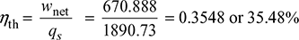
Net work, wnet = wt − wp = 823.824 − 152.936 = 670.888 kJ/kg
Heat supplied, qs = h1 − hf4 = 2799.5 − 908.77 = 1890.73 kJ/kg
- Thermal efficiency
- Work ratio,
- Specific steam consumption,
Leave a Reply