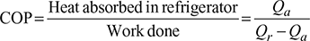
The reversed Carnot cycle is shown in Fig. 18.3 on p-v and T-s. diagrams. The sequence of operations is given below:
- The process 1-2 represents the isentropic compression of the working fluid with the aid of external work. The temperature of the working fluid rises from T1 to T2.
- The process 2-3 represents the isothermal compression of the working fluid during which heat Qr is rejected at constant high temperature T2.
- The process 3-4 represents the isentropic expansion of the working fluid. The temperature of working fluid drops from T2 to T1.
- The process 4-1 represents the absorption of heat Qa by the working fluid from refrigerator at constant low temperature T1 during isothermal expansion.

The Carnot cycle is practically not feasible since isothermal energy rejection requires extremely slow motion followed by isentropic process during which the piston should move at extremely faster rate, which is mechanically not obtainable.
The COP of reversed Carnot cycle is the highest of all refrigeration cycles. COP increases as T1 is increased or T2 is lowered. The increase in COP for increased T1is more than for decreased T2. Since T2 in winter is less than T2 in summer therefore COP in winter is more than that of in summer.
If the cycle is used as a heat pump, then energy performance ratio,

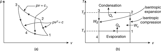
Figure 18.3 Reversed Carnot cycle: (a) p-v diagram, (b) T-s diagram
Leave a Reply