In a binary vapour cycle, two working substances are used—one with good characteristics at high temperature and the other with good at low temperature characteristics. Figures 4.23(a) and (b) show two Rankine cycles in a combined arrangement. The heat is rejected from the high temperature cycle (mercury cycle) as energy supplied to the low temperature cycle (steam cycle). This occurs in a heat exchanger which functions as the condenser for mercury cycle and boiler for the water cycle. Specific enthalpy increase of water as it passes through the heat exchanger is several times the magnitude of the specific enthalpy decrease of mercury. Thus, the mass of mercury circulated in mercury cycle is several times more than mass of water in the water cycle. Binary vapour power cycles have a great advantage of its operation at high average heat addition temperature than conventional water cycles and give higher thermal efficiency.
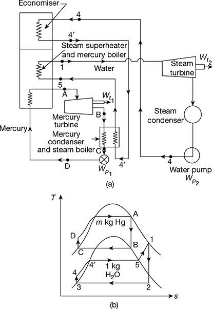
Figure 4.23 Binary vapour cycles: (a) Schematic diagram, (b) Mercury and steam cycles
Mercury cycle A−B−C−D−A is a simple Rankine cycle using saturated vapour. Heat is supplied to mercury in the process D−A. Mercury expands in process A−B and is condensed in process B−C. Mercury-saturated liquid is compressed in feed pump from condenser pressure to boiler pressure in process C−D. Thus, the Rankine cycle on mercury is completed.
Heat rejected during condensation in the mercury condenser is supplied to water to transform water into saturated steam in process 4−5. Process 4−5 may take place partly in the economiser located in the exhaust gases of mercury boiler and partly in the mercury condenser. The saturated vapour is superheated in the superheater located in the mercury boiler furnace process 5−1. Ideal process 4−4′occurs in the economiser and 4′−5 in the mercury condenser. Superheated steam expands in the turbine, process 1−2, and then condenses in the steam condenser, process 2−3. The condensate or feed water is then pumped by process 3−4, and heated till it is saturated liquid in the economiser as shown by process 4−4′, before going to the mercury condenser – steam boiler where enthalpy of evaporation is absorbed.
Let m = flow rate of mercury in the mercury cycle for 1 kg steam being circulated in steam cycle.
Heat added, Qa = m (hA − hD) + (h1 − h5) + (![]() − h4)
− h4)
Heat rejected, Qr = (h2 − h3)
Workdone by steam and mercury turbines,
Wt = m (hA − hB) + (h1 − h2)
Workdone on the feed pumps for mercury liquid and water,
Wp = m (hD − hC) + (h4 − h3)
Thermal efficiency of binary cycle,


The mercury cycle is known as topping cycle and the steam cycle is known as bottoming cycle.
Example 4.10
A binary vapour cycle consists of two ideal Rankine cycles with mercury and steam as working substances. The following data is given:
Saturated mercury vapour pressure at entry to turbine = 4.5 bar
Mercury vapour exit pressure from turbine = 0.04 bar
Saturated steam generated in mercury condenser pressure = 15 bar
Steam superheated temperature in superheater in mercury boiler = 300°C
Condensate water pressure pumped through economiser located in exhaust flue of mercury boiler to saturation temperature = 15 bar
Isentropic efficiency of mercury turbine = 0.85
Isentropic efficiency of steam turbine = 0.88
Calculate (a) the overall thermal efficiency of the cycle and (b) the rate of flow of mercury turbine in kg/h.
Properties of saturated mercury
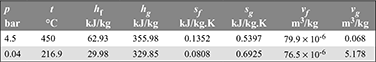
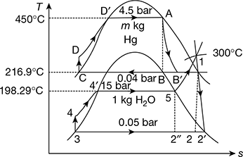
Figure 4.24 Hg − H2O binary vapour cycle
Solution
Refer to Fig. 4.24.
Mercury cycle
hA = 3559 kJ/kg, pA = 4.5 bar, tA = 450°C, sA = 0.5397 kJ/kg.K
Now sA = sfB + xB (sgB − sfB)
or 0.5397 = 0.0808 + xB (0.6925 − 0.0808)
or xB = 0.75
hB = hfB + xB (hgB − hfB) = 29.98 + 0.75 (329.85 − 29.98) = 254.88 kJ/kg
hB′ = hA − (hA − hB) ηt1 = 355.98 − (355.98 − 254.88) × 0.85 = 270.04 kJ/kg
pB′ = 0.04 bar, tB′ = 216.9°C
hc = hfc = 29.98 kJ/kg, tc = 216.9°C
hD = hc + vfc (pD − pC) × 102 = 29.98 + 76.5 × 10⁻⁶ (4.5 − 0.04) × 102 = 30.0142 kJ/kg
wp1 = vfc (pD − pC) × 102 = 0.03412 kJ/kg
Steam cycle
p1 = 15 bar, t1 = 300°C, h1 = 3038.9 kJ/kg, s1 = 6.9207 kJ/kg. K
p2 = 0.05 bar, hf2 = 137.77 kJ/kg, hg2 = 2561.6 kJ/kg, sf2 = 0.4763 kJ/kg.K,
h5 = 2789.9 kJ/kg, h4′ = 844.66 kJ/kg
hfg2 = 2423.8 kJ/kg, sg2 = 8.3960 kJ/kg.K, vf2 = 0.0010052 m3/kg
s1 = s2 = sf2 + x2 sfg2
or 6.9207 = 0.4763 + x2 (8.3980 − 0.4763)
or x2 = 0.8137
h2 = hf 2 + x2hfg2 = 137.77 + 0.8137 × 2423.8 = 2110 kJ/kg
h2′ = h1 − (h1 − h2) ηt2 = 3038.9 − (3038.9 − 2110) × 0.88 = 2221.47 kJ/kg
h3 = hf3 = 137.77 kJ/kg
wp2 = vf 3 (p4 − p3) × 102 = 0.0010052 (15 − 0.05) × 102 = 1.503 kJ/kg
h4 = h3 + wp2 = 137.77 + 1.503 = 139.27 kJ/kg

Total heat added, (qa)total = mHg (hA − hD) + 1 [(h1 − h5) + h4′ − h4)]
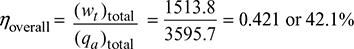
= 8.103 (355.98 − 30.0142) + 1 [(3038.9 − 2789.9) + (844.66 − 139.27)] = 3595.7 kJ/kg
Work done, (wt)Hg = mHg (hA − hB′) = 8.103 (355.98 − 270.04) = 696.37 kJ/kg of steam
(wt)steam = 1 × (h1 − ![]() ) = 1 × (3038.9 − 2221.47) = 817.43 kJ/kg
) = 1 × (3038.9 − 2221.47) = 817.43 kJ/kg
(wt)total = 696.37 + 817.43 = 1513.8 kJ/kg
Neglecting pump work being very small,
Considering pump work,

Leave a Reply