The Bell-Coleman air refrigeration cycle was developed by Bell-Coleman and Light Foot by reversing the Joule’s or Brayton’s air cycle. The schematic diagram of such a cycle is shown in Fig. 18.8. It consists of a compressor, a cooler, an expander, and a refrigerator. The p-v and T-s diagrams are shown in Fig. 18.9.
- Process 1-2: Isentropic compressionThe cold air from the refrigerator is drawn into the compressor cylinder where it is compressed isentropically. The pressure and temperature of air increases and the specific volume decreases from v1 to v2. No heat is absorbed or rejected by the air.
- Process 2-3: Constant pressure coolingThe warm air from the compressor is passed into the cooler where it is cooled at constant pressure p3 = p2. The temperature decreases from T2 to T3 and specific volume reduces from v2 to v3.Heat rejected by air, q2–3= cp(T2 − T3)
- Process 3-4: Isentropic expansionThe air from the cooler is drawn into the expander cylinder where it is expanded isentropically from p3 to p4. The temperature falls from T3 to T4 and specific volume increases from v3 to v4. No heat is absorbed or rejected by air during this process.
- Process 4-1: Constant pressure expansionThe cold air from the expander is passed to the refrigerator where it is expanded at constant pressure p4 = p1.The temperature of air increases from T4 to T1 and specific volume increases from v4 to v1.Heat absorbed by air (or extracted from the refrigerator), q4−1 = cp (T1 −T4)
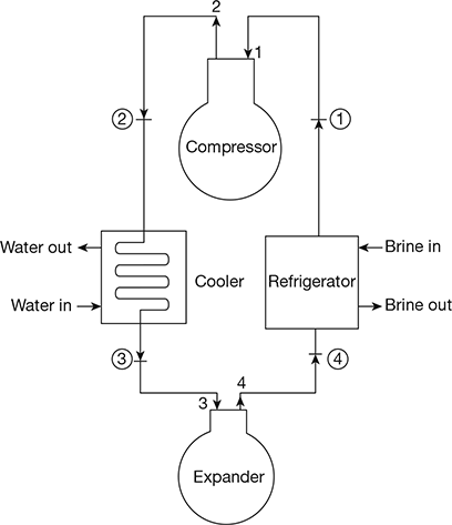
Figure 18.8 Schematic diagram of Bell-Coleman air refrigeration cycle
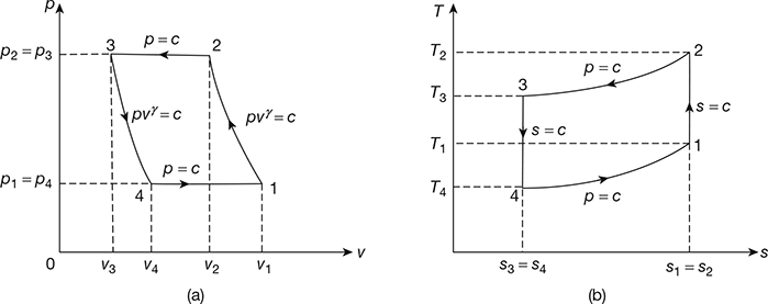
Figure 18.9 Bell-Coleman cycle: (a) p-v diagram, (b) T-s diagrame
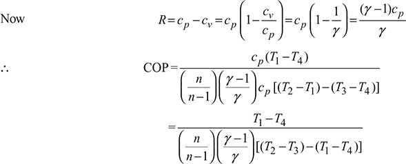
Work done during the cycle per kg of air,
W = Heat rejected − Heat absorbed
= q2−3 − q4−1 = cp[(T2 −T3) −(T1 −T4)]
For isentropic compression process 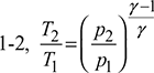 and for isentropic expansion process 3-4,
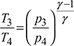
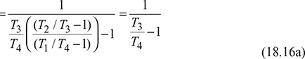
Since p2 = p3 and p1 = p4, therefore, ![]()
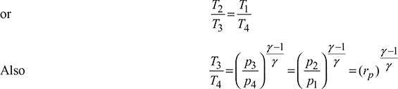
where ![]()

1 Bell-Coleman Cycle with Polytropic Processes
Let the compression and expansion processes take place according to the polytropic law. pvn = const.
- Process 1-2: Polytropic compressionWork done per kg of air,
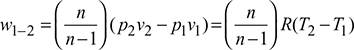
- 2. Process 3-4: Polytropic expansion
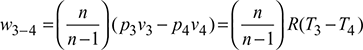 Net work done during the cycle per kg of air,
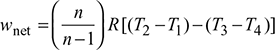
- Heat absorbed during constant pressure process 4-1.
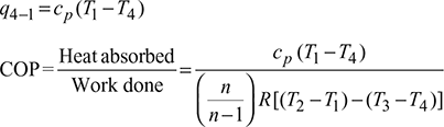
- For n = γ, Eq. (18.17) reduces to Eq. (18.16b)For n < γ, (COP)poly > (COP)isenFor n > γ, (COP)poly < (COP)isen
Example 18.7
A closed cycle refrigeration system working between 5 bar and 20 bar extracts 144 MJ of heat per hour. The air enters the compressor at 6°C and the expander at 22°C. The unit operates at 320 rpm. Calculate by assuming isentropic compression and expansion:
- Power required to operate the unit.
- Bore of compressor, and
- Refrigerating capacity in tonnes of ice at 0°C per day.
The following data is available:
| Stroke for double acting compressor and expander | = 300 mm |
| Mechanical efficiency of compressor | = 80% |
| Mechanical efficiency of expander | = 85% |
Solution
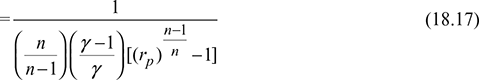
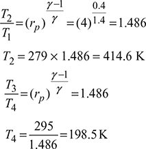
Given: p1 = p4 = 5 bar, p2 = p3 = 20 bar, Q4-1 = 144 MJ/h or 2400 kJ/min, T1 = 273 + 6 = 279 K, T3 = 273 + 22 = 295 K, N = 320 rpm, L = 300 mm, ηc = 0.80, ηe = 0.85, = 1.4
For p-v and T-s diagrams, refer to Fig. 18.9.
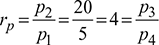
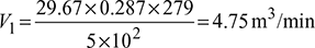
 Heat extracted from the refrigeration system per kg of air, q4−1 = cp (T1 −T4)=1.005 (279 −198.5) =80.9 kJ/kgMass of air circulated,
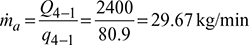 Work done during isentropic compression process 1-2,
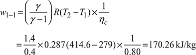 Work done during isentropic expansion process 3-4,
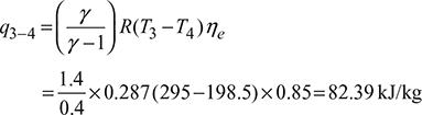 Net work done per kg of air supplied to the system, qnet = w1−2 −w3−4 =170.26 −82.39=87.87 kJ/kgPower required to operate the system,
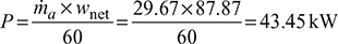
- p1V1 =maRT1
 Also
Also 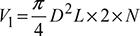 (for double acting compressor)
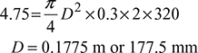
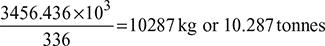
- Refrigerating capacity of the system per day = q4−1 ×ma ×60 × 24= 80.9 × 29.67 × 60 × 24 = 3456.436 MJAssuming latent heat of ice = 336 kJ/kgIce formation capacity of system =
Example 18.8
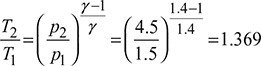
A closed cycle reversed Brayton refrigerator is required for a capacity of 12TR. The cooler pressure is 4.5 bar and the refrigerator pressure is 1.5 bar. The air is cooled in the cooler at a temperature of 45°C and the temperature of air at inlet to compressor is 20°C. Calculate for the ideal cycle: (a) COP, (b) mass of air circulated per minute, (c) theoretical displacement of compressor piston, (d) theoretical displacement of expander piston, and (e) net power per tonne of refrigeration. The compression and expansion are isentropic.
Solution
Given: Q = 12TR, p1 = p4 = 1.5 bar, p2 = p3 = 4.5 bar, T1 = 273 − 20 = 253 K, T3 = 273 + 45 = 318 K.
The p-v and T-s diagrams are shown in Fig. 18.10.
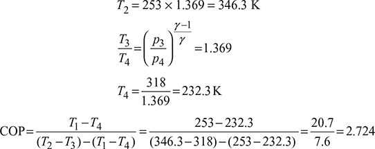
- Heat extracted per minute, Q = 211 × 12 = 2532 kJ/minHeat extracted from the refrigerator per kg of air, q = cp (T1 −T4)=1.005(253 − 232.3)= 20.8 kJ/kg
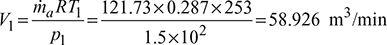
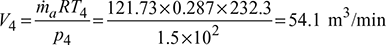
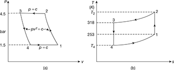 Figure 18.10 Reversed Brayton cycle: (a) p-v diagram, (b) T-s diagramMass of air circulated,
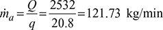
- Work done per minute = ṁa (Heat rejected – Heat extracted)= ṁa cp [(T2 − T3) − (T1 −T4)]= 121.73 × 1.005 [(346.3 – 318) – (253 – 232.3)]= 929.77 kJ/minNet power per tonne of refrigeration =
Example 18.9
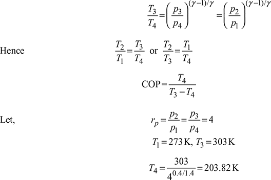
Dense air is used as refrigerant in Reverse-Brayton or Bell-Coleman or Joule cycle. Draw T-s and p-v diagrams for the cycle. Derive the expression for COP in terms of pressure ratio. If temperatures at the end of heat absorption and heat rejection are 0°C and 30°C respectively, the pressure ratio is 4 and the pressure in the cooler is 4 bar determine the temperatures at all state points and volume flow rates at inlet to compressor and at exit of turbine for 1 TR cooling capacity.
Solution
The T-s and p-v diagrams are shown in Fig. 18.11(a) and the schematic diagram in Fig. 18.11(b).
qr = q2−3 = cp (T2 −T3)
qa = q4−1 = c4−1 (T1 −T4)
Work done = qr − qa = cp (T2 − T3) − cp (T1 − T4)
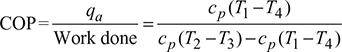
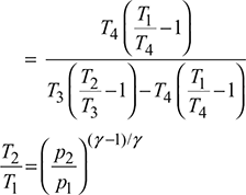
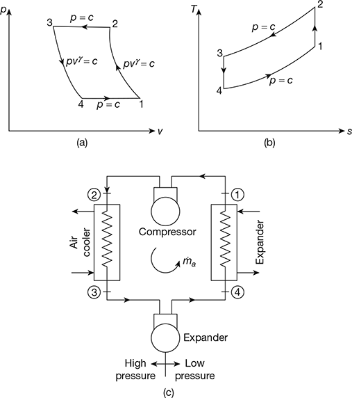
Figure 18.11 Bell–Coleman cycle: (a) p-v diagram, (b) T-s diagram, (c) Schematic diagram
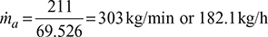
Heat extracted per minute = 1 × 211 = 211 kJ/min
Heat extracted from cold chamber per kg of air
= cp(T1 − T4) = 1.005 × (273 − 203.82) = 69.526 kJ/kg
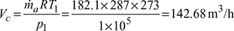
Mass flow rate of air,
Volume handled by the compressor,
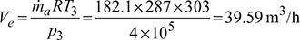
Volume handled by expander,
Example 18.10
An air refrigeration used for food storage provides 30 TR. The temperature of air entering the compressor is 10°C and temperature at exit of cooler is 30°C. Calculate:
- COP of the cycle, and
- Power required per tonne of refrigeration by the compressor.
The quantity of air circulated in the system is 3600 kg/h. The compression and expansion processes follow the law pv1.3 = const. and γ = 1.4, cp = 1.005 kJ/kg.K for air.
Solution
Given: Q = 30 TR, T1 = 273 + 10 = 283 K, T3 = 273 + 30 = 303 K, ṁa = 3600 kg/h, n = 1.3
- Heat extracted from the refrigerator, Q = 30 × 211 = 6330 kJ/min
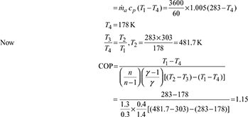
- Heat absorbed,
 Work done per minute,
 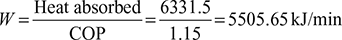 Power required per ton of refrigeration
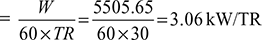
Example 18.11
A dense air refrigeration cycle operates between pressures of 4 bar and 20 bar. The air temperature after heat rejection to surroundings is 40°C and air temperature at exit of refrigeration is 8°C. The isentropic efficiencies of compressor and expander are 0.82 and 0.86 respectively. Determine the compressor and expander work per TR. COP, and power required per TR. Take γ = 1.4 and cp = 1.005 kJ/kg.K.
Solution
Given: p1 = p4 = 4 bar, p2 = p3 = 20 bar, T3 = 273 + 40 = 313 K, T1 = 273 + 8 = 281 K, ηc = 0.82, ηe = 0.86, γ = 1.4, cp = 1.005 kJ/kg.K.
The p-v and T-s diagrams are shown in Fig. 18.12
Process 1-2: Isentropic compression
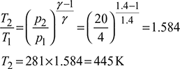
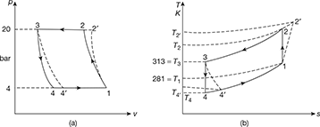
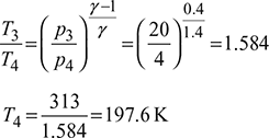
Figure 18.12 Dense air refrigeration cycle: (a) p-v diagram, (b) T-s diagram
Process 3-4: isentropic expansion
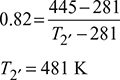
Isentropic efficiency of compressor, ![]()
Isentropic efficiency of expander, ![]()
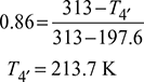
Refrigerating effect per kg of air, q4′–1 = cp(T1 − T4′) = 1.005 (281 − 213.7) = 67.6 kJ/kg
Mass flow rate of air, ![]()
Compressor work per TR, Wc = ṁacp (T2′ − T1) = 3.12× 7.005(481− 281)= 627.12 kJ/min
Expander work per TR, We = ṁacp (T3 − T4′) = 3.12×1.005(313− 213.7)= 311.36 kJ/min
Net work done, Wnet = Wc − We = 627.12 − 311.36 = 315.76 kJ/min
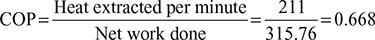
Power required per TR =![]()
Leave a Reply