The application of the brake by pressing the brake pedal makes the compressed air flow through the delivery port from the supply port. For the front brake circuit, the air in the delivery chamber flows through the pipelines to the frontal brake chamber which is mounted on the front axles of the vehicle. The top bottom supply ports are linked to rear and front reservoirs respectively, while the top and bottom delivery ports are coupled to relay valve and front chambers respectively. Whenever the driver applies force to the plunger, the force transmits to the top piston thereby compressing the rubber plunger spring at the top chamber. If the force applied on the top piston is higher than that of preload and friction, the top piston will move downwards. Meanwhile the exhaust port will be blocked when the top piston makes contact with the top valve, and whenever the force supplied to the top valve can prevail over the preload on the top valve, the inlet port will tend to open. The pressure was kept constant for both the inlet and exhaust ports when closed, thus the air pressure in the top chamber was maintained constant. If the driver reduces the force in the pedal, the balance of the top piston will be broken. The top piston moves up for the force made by compressed air when it is larger than pedal force.
Components of the Typical Air Brake System
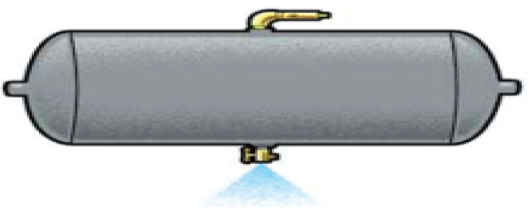
1. Compressor and storage reservoirs
Air compressor is the primary energy source for a typical air braking system. Highly pressurized air from the compressor is securely stored in the storage reservoirs or storage tanks where it is allowed to cool down to ambient temperature. The foreign particles and impurities can be expunged from the storage reservoirs by the automatic drain valve.
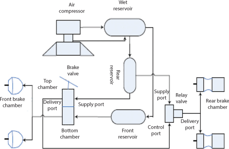
2. Treadle valve:
The treadle valve (brake application valve) modulates the amount of air supplied to the brake chambers from the storage reservoirs. The advantage of a dual circuit treadle valve is that partial braking is still possible in the event of failure of one of the two circuits.
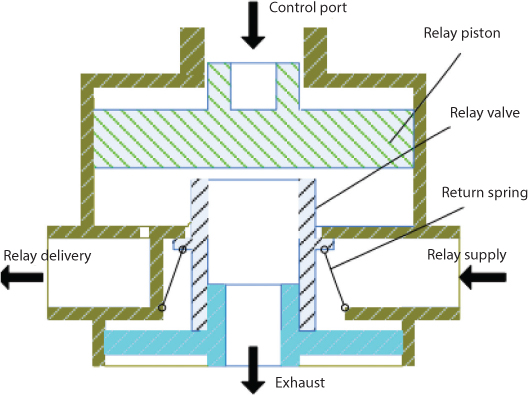
3. Quick release valve and relay valve:
A quick release valve is mounted on the front axle of the tractor and the air from the secondary circuit of the treadle valve passes through it en route to the two front brake chambers. It facilitates the quick exhaust of the air from the front brake chambers when the brake pedal is released by the driver. The relay valve also helps in the quick exhaust of air from the rear brake chambers when the brake pedal is released by the driver.
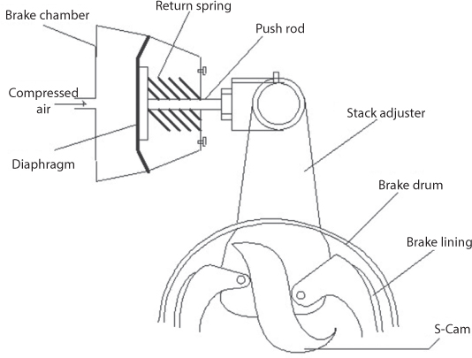
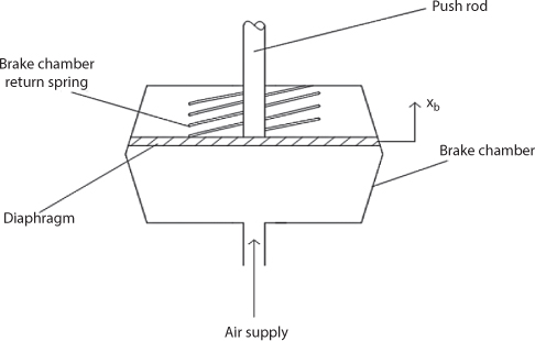
4. Brake chambers
The brake chambers transfer the input energy from the pressurized air into a mechanical energy that shifts the push rod which in turn activates the foundation brakes.
5. Automatic slack adjuster: it converts translation motion of push rod into rotation of cam shaft. The force from rake chamber falls as the stroke of push rod exceeds its highest levels.
6. Foundation brakes: These units retard the motion of the vehicle and are operated using safety valves which stop building of excessive pressure in storage reservoirs.
7. Drainage valve: Removes dirt
8. Low pressure switch: Keeps an eye on air pressure
9. Parking brake control valve: Used to apply the parking brakes.
10. Pushrod: Transmits the force to the slack adjuster.
11. S-cam: Moves the brake pads during brake application
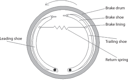
12. Drum-brake: Consists of two brake–shoes and lining supported on a back plate bolted to the axle-casing
Leave a Reply