1 Summer Air-conditioning System with Ventilation
Air and Zero By-pass Factor
The schematic arrangement of summer air-conditioning system with ventilation without by-pass factor is shown in Fig. 20.33. The outside air flows through the damper and mixes with the recirculated air. The mixed air then passes through the filter to remove dirt and dust and then through cooling coil whose temperature is kept much below the DBT of air in the conditioned space. The cooled air then passes through a perforated membrane where it losses its moisture in the condensed form. The moisture is collected in a sump. After that, the air is made to pass through a heating coil which heats the air slightly as per the requirement of designed air DBT and RH. Now the conditioned air is supplied to the room by a supply air fan. From the room a part of the used air is exhausted to the atmosphere by ventilation. The remaining part of the used air (recirculated air) is mixed with fresh air for conditioning.
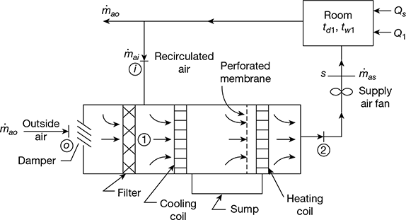
Figure 20.33 Schematic diagram of system with ventilation air without bypass factor
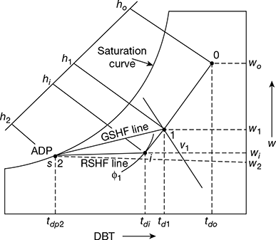
Figure 20.34 Summer air conditioning process with ventilation air without BPF
Figure 20.34 shows the air-conditioning processes.
o, i = outside and inside air states respectively
1 = state of air after mixing recirculated room air with ventilation air
ṁai, ṁa0 = mass flow rate of recirculated room air and ventilation air respectively
2 = supply air state for a minimum rate of supply air
line i-2 = ADP, tdp2
= RSHF line
line 1-2 = GSHF line
ṁas = mass flow rate of mixture air
Q̇ = ṁas(hi − h2) + (ṁai hi + ṁao ho)
(ṁas − ṁao)hi + ṁao ho − ṁas h2

= RTH + OATH
- Ventilation loadLet (cmm)o = outside ventilation air volume flow rate = ṁas × vo


- Room loadLet (cmm)1 = mixture air volume flow rateṁa1 = ṁai + ṁao = ṁas
 RTH = RSH + RLH
 - Air-conditioning equipment loadTSH = RSH + OASHTLH = RLH + OALHGTH = TSH + TLH

2 Summer Air-conditioning System with Ventilation Air
and By-pass Factor
The summer air-conditioning processes with ventilation air and BPF is shown Fig. 20.35.

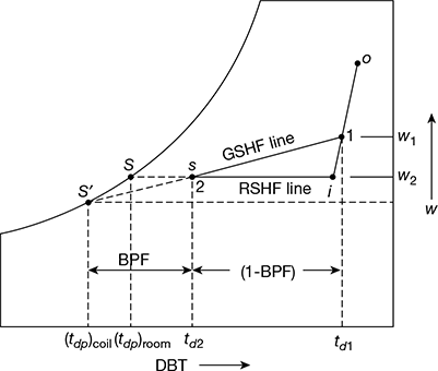
Figure 20.35 Summer air-conditioning processes with ventilation air and BPF
3 Winter Air-conditioning System
The schematic arrangement of winter air-conditioning system is shown in Fig. 20.36. The outside air flows through a damper and mixes up with the recirculated air. The mixed air passes through a filter to remove dirt, dust and other impurities. The air now passes through a preheating coil to prevent the possible freezing of water and to control the evaporation of water in the humidifier. Then the air is passed through a reheating coil to bring the air to the designed DBT. This conditioned air is supplied to the room by means of a supply an fan. From the room, a part of the used air is exhausted to the atmosphere and the remaining part is recirculated again.
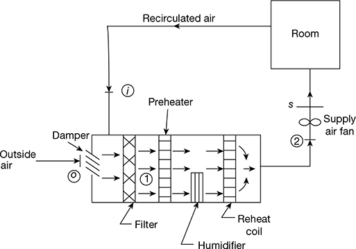
Figure 20.36 Winter air-conditioning system
The air-conditioning processes are shown in Fig. 20.37.
Process 1-2: Preheating
Process 2-3: Adiabatic saturation.
Process 1-3: Heating and humidifying air in air washer with pumped recirculation and external heating of water.
Process 3-s: Reheating
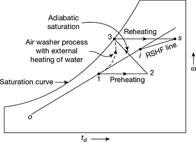
Figure 20.37 Winter air-conditioning processes
Example 20.11
Air at 10°C DBT and 90% RH is to be brought to 35°C DBT and 22.5°C WBT with the help of winter air-conditioner. If the humidified air comes out of the humidifier at 90% RH, determine: (a) the temperature to which the air should be preheated, and (b) the efficiency of the air washer.
Solution
Given: td1 =10°C, ϕ1 = 90%, tds = 35°C, tws = 22.5°C
The psychrometric processes are shown in Fig. 20.38
Locate point l(tdl, ϕ1) and point s(tds, tws).
Draw horizontal lines from points 1 and s. From point 3 draw WBT = const. line to locate point 2.
From psychrometric chart, the temperature to which air should be preheated
td2 = 31.2°C
td3 = 18.5°C and td3′ = 17.5°C
Efficiency of air-washer =![]()
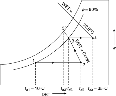
Figure 20.38
4 Comfort Air-conditioning System
In comfort air-conditioning, the air is brought to the required DBT and RH for the human health, comfort and efficiency. The comfort conditions have been discussed in detail in art. 20.11.1. Normally it is assumed to be 21°C DBT and 50% RH. The SHF is generally kept between 0.7 to 0.9. The comfort air-conditioning may be adopted for homes, offices, shops, restaurants, theatres, hospitals, schools, etc.
5 Industrial Air-conditioning System
In an industry the inside DBT and RH of air have to be kept constant for proper working of the machines and manufacturing processes. Special type of air-conditioning systems have to be provided for textile mills, paper mills, machine-parts manufacturing plants, tool rooms, CNC machining centres, photo-processing plants, etc.
Example 20.12
Atmospheric air at a pressure of 1-0132 bar has a dry bulb temperature of 30°C and Relative Humidity of 70%. Calculate:
- partial pressure of Water Vapour and air in moist air,
- the specific humidity,
- the degree of saturation, and
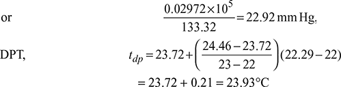
- the Dew Point temperature.
Solution
Given: pb = 1.0132 bar, td = 30°C, ϕ = 70%
- Corresponding to td = 30°C, saturation pressure of water vapour, from steam tables, isps = 0.04246 bar,
 Now pb = pa + pvPartial pressure of air, pa = 1.0132 − 0.02972 = 0.98348 bar
 - Specific humidity,

- Specific humidity of started air:
 Degree of saturation,
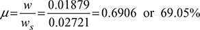
- DPT = saturation temperature corresponding to pv = 0.02972 barFrom steam tables, corresponding to pv = 0.02972 bar
Example 20.13
In a laboratory test on a particular day, a psychrometer recorded the dry bulb and wet bulb temperatures for atmospheric air as 35°C and 25°C respectively. The atmospheric pressure is 1.013 bar 1. Calculate:
- the relative humidity,
- the specific humidity,
- the dew point temperature, and
- the degree of saturation.
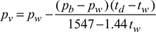
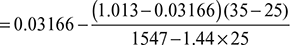
The partial pressure of water vapour (pv) can be calculated with the help of Carrier’s Equation, given as;
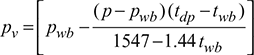
where pwb = Saturation pressure corresponding to wet bulb temperature,
p = Barometric pressure, and
tdb and twb = are the dry bulb and wet bulb temperatures of air (in 0°C).
Gas constant of air, Ra = 0.287 kJ/kg.K.
Solution
Given: td = 35°C, tw = 25°C, pb = 1.013 bar,
- Corresponding to td = 35°C, ps = 0.5622 bar, and for tw = 25°C, pw = 0.03166 barPartial pressure of water vapour,
 Relative humidity,
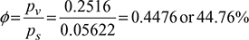
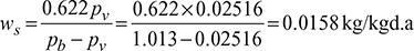
- Specific humidity,
- Corresponding to pv = 0.02516 bar,

- Specific humidity of saturated,
 Degree of saturation,
Leave a Reply