To answer this let us consider for the sake of simplicity that only one FWH is used. The aim of using any feed water heater is to heat the feed water as close to the boiler temperature as possible. We may now place the feed water heater at position 1, 2 or 3. TB and TC are saturation temperatures at boiler and condenser pressures respectively. Now at position 1 the heat transfers are because of temperature differences TB – T1 and T1 – TC.
At position 3 the heat transfers are because of TB – T3 and T3 – TC. In either case one of the temperature differences is very large. To minimise the temperature differences, we have to select position 2 which is in the middle i.e., TB – T2 = T2 – TC.
Thus we find the temperature which is halfway between TB and TC and then obtain the saturation pressure at that temperature. Feed water placed at this pressure gives us optimum position of maximum efficiency. Note that the temperature at which steam is actually bled from the turbine may be superheated.
If two FWHS are used, the temperature range TB – TC is divided into three equal parts and for three FWHS it is divided into 4 equal parts.
Thus, in general, for n FWHS the optimum temperature rise per heater would be given by –

Consider for example a cycle where boiler pressure is 100 bar and condenser pressure is 0.08 bar and three FWHS are to be used. We find the pressures at which they are placed. From steam tables we get saturation temperatures at 100 bar and 0.08 bar. They are TB = 310.96°C and TC = 41.534°C respectively. From above Eq. (22.14) we have –
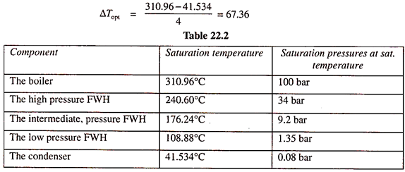
Thus the saturation temperatures of FWHS will be found by adding ΔTopt successively from TC = 41.534 onwards and then finding the corresponding saturation pressures from the steam tables. Table 22.1 summarises the results.
Thus, the FWHS will be placed at 34 bar, 9.2 bar and 1.35 bar respectively.
Leave a Reply