The advent of high speed passenger aircraft, jet aircraft and missiles has introduced the need for compact and simple refrigeration systems capable of high capacity with a minimum reduction of payload. When the power requirements needed to transport the additional weight of the refrigerating system are taken into account, air cycle system usually prove to be most efficient. In fact, some modern air refrigeration systems weight as low as 2 kg per ton of refrigeration.
In passenger aircraft and missiles following are the sources of heat coming into the cabins:
(i) Surface friction heat because of the high speeds of air-crafts or missiles.
(ii) Heat dissipated by electrical equipment used in the air craft and missiles.
(iii) Heat convected and radiated in addition to friction heat.
(iv) In passenger air-crafts, heat entering the cabins because of the hot tea, coffee and meals served.
The heat, thus entering the aircraft or missiles has to be removed by providing refrigeration.
The different systems of air refrigeration provided to the aircraft and missiles are:
(i) Simple air cycle-evaporating cooling system.
(ii) Bootstrap air-cycle cooling system.
(iii) Reduced ambient air-cycle system.
The schematic diagrams of these systems are given below without elaborating much the working of these systems.
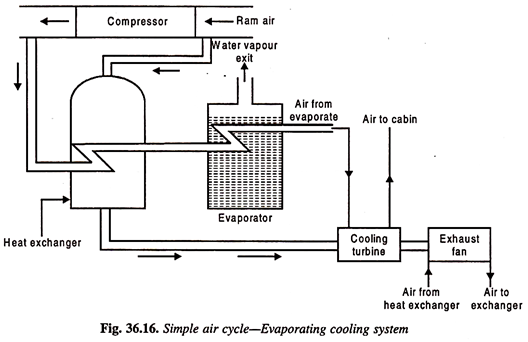
1. Simple Air Cycle-Evaporating Cooling System:
Ram air is at lower temperature than compressed air and hence compressed air is cooled by ram air in heat exchanger. Ram air is inducted by a cooling fan. This fan is driven by the cooling turbine as shown in Fig. 36.16. Compressed air leaves the heat exchanger and is passed through the evaporator where water is evaporated and the heat required is taken from the air and is cooled. This air is expanded through a cooling turbine and this air is supplied to the cabin.
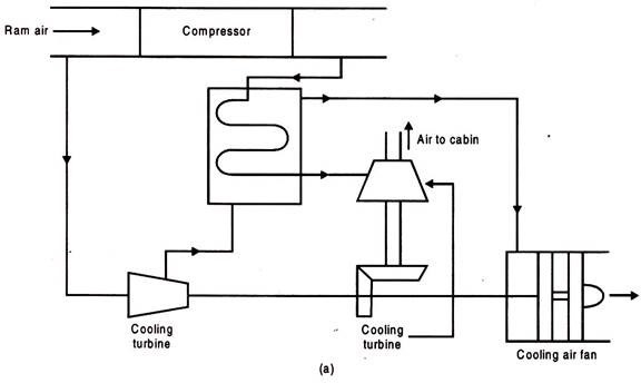
2. Bootstrap Air-Cycle Cooling System:
This system is shown in Fig. 36.17 (a) and (b). The cycle is shown on T-S diagram.


The cycle is shown on T-S diagram:
1- 2 Ramming effect.
2- 3 Main compression.
3- 4 Cooling in first H-E.
4- 5 Compression in secondary compressor.
5- 6 Cooling second HE.
6- 7 Expansion in cooling turbine.
3. Reduced Ambient Air-Cycle Cooling System:
This system is diagrammatically shown in Fig. 36.18 (a) and T-S diagram of Fig. 36.18 (b).

1- 2 Ramming effect.
2- 3 Compression in main compressor.
3- 4 Cooling in heat exchanger.
4- 5 Expansion in the cooling turbine.
Leave a Reply